mrekim
Apr 18, 2014Explorer
Re-Wiring the brakes.
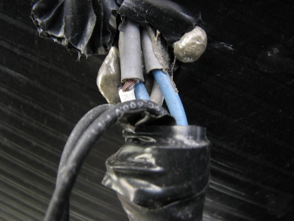
My 35' ~10,000 lb GVWR trailer brakes were wired with 14 gauge wire and very poor crimps. All the crimps on that I've seen so far are pretty bad...
I'm going to redo it with a quality crimp tool and marine heat shrink connectors.
Does anyone know the wire size of the brake magnets(I need to order crimp connectors....) ? My trailer has 5200 lb Lippert axles. I might have a magnet from a 7,000 lb Dexter stashed away somewhere. Is it likely the magnet wires are the same size?
I've seen a few threads on the topic:
LAdams: I rewired my trailer brakes
JBarca: Independent Brake Wire Feed Upgrade
I like the idea of a star configuration and will go with that. It seems as if running 10G to the axles and then building the star from there is the approach most often taken.
What about running 14 or even 16 Gauge wire from each of the 4 brake magnets all the way from each wheel to the tongue - basically using 4 smaller gauge wires, but only 3 amps per and a "home run" wiring approach back to the tongue. I'm trying to avoid hiding junction boxes in the corplast...