your drawing was not to far off
here is the parallel changes
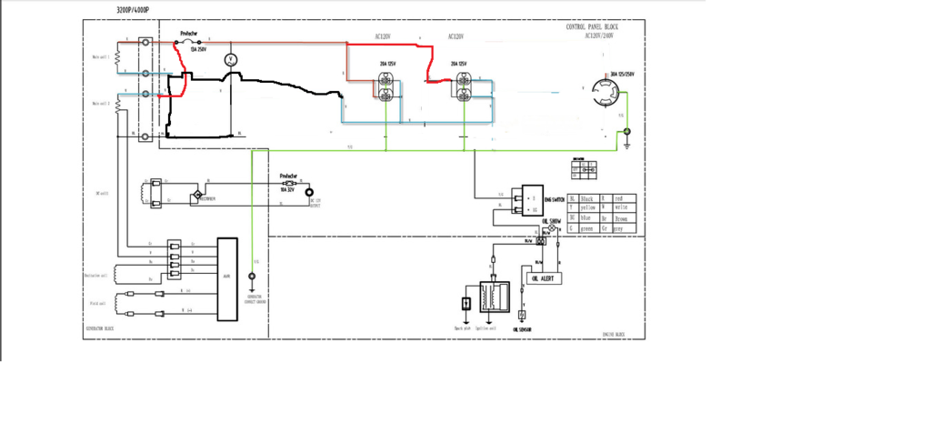
red is hot
black to blue is the neutral side
parallel means you parallel the windings, you have to break the center tap neutral and make new connections, the neutral & hot of the second lower pair switch places
i erased the lower / 2nd circuit breaker (it would now be in the neutral)
that needs to be rewired, both breakers go side by side together on the top red/hot
or replace the them with one 25amp breaker
remove the grd neutral bond inside the genset
i removed the twist lock completely
although that one or another one could be connected for 120v 25amp
twist lock
the avr measures both windings instead of just one {because the are wired in phase parallel}
OEM stock was series windings for 230v with center tap for neutral
this should work Unless there is some wire for the Avr deliberately missing from the circuit drawing
edit:
there is the possibilty that in the stock wiring the AVR is measuring the difference between the center tapped "bonded to ground", and its connection point in the winding,
switching that center tap neutral to a hot changes the reference voltage,
if the above drawing does not work, aka low voltage
contact me for a new drawing
reverseing the pahses and connectons