MrWizard wrote:
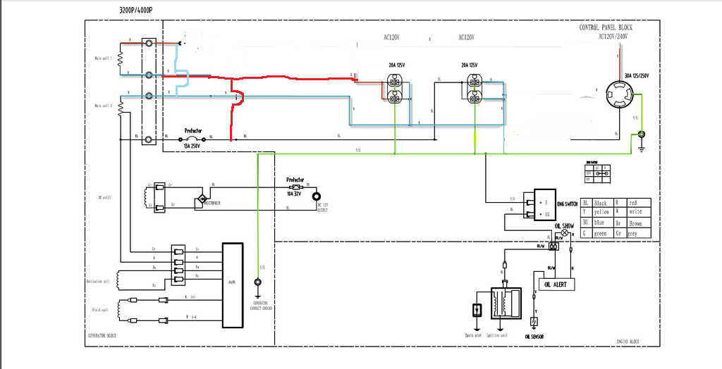
its two 120v windings
the voltage is the same in each winding
if it doesn't work,,and thats.. IF
then it is because the in the original configuration the avr was measuring between grd reference (center tap power windings neutral bonded to grd) and the tap point
the fix for that is to reverse the (as drawn) hot and neutral wires at the outlets
and bond that (new)neutral (the old hot) to the grd
creating a bonded neutral for reference point
just like the oem configuration except with parallel windings
i'll make a new drawing for this
use it only IF the the current drawing does not work
don't forget the double parallel circuit breakers in the hot side
must be both in the hot side, not hot and neutral, and not only one side, both hots must go thru a breaker before the receptacles
this drawing does not show the second breaker it must be in line of the first hot before they join
this drawing switches the phase of winding#1 instead of winding#2
this should work no matter what they are doing with the AVR
i don't like bonded neutrals on portable generators,
IMO ..its a safety hazard
Had a thought on the AVR..
Need to find out what the voltage sample is.. Then sub in a step down transformer with a secondary voltage that is close to what the AVR is needing.
Wire the primary of the step down to your 120V output, one would also need to make sure the transformer output has a ac waveform in phase with what the AVR is expecting..
I am pretty sure the reason the OP was not able to make it work is due to the way they tapped the winding for the AVR..
If the OP did not observe the correct phasing, the AVR may not be getting the correct sample in either voltage or phase.. Not sure how sensitive it may be to the phase..