DryCamper11 wrote:
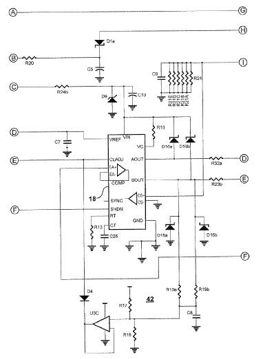
In case anyone is interested, the bottom of this circuit, marked 42 is protection for the PD in case the output gets short circuited. The CLADJ pin (Current Limit Adjust) sets the maximum current.
CLADJ at the left encircled E is connected to circuit 42 and to a voltage divider (see one of the other posts showing the input circuit) that sets the max current limit under normal operation. If the output was short circuited and only the voltage divider max current limit were set, the PD would try to put its max current (but no more) through the short circuit. It would hit the max current limit for each cycle almost immediately at the start of each cycle, and the duty cycle would drop to near zero, but the output current would be at the max limit.
Circuit 42 acts as a foldback circuit to prevent this max current output during a short circuit. As the duty cycle of AOUT (pin 11) and BOUT (pin 14) decreases, the voltage of capacitor C8 decreases. The voltage at the output of U3C will then be lower than the voltage between the resistors in the current limit voltage divider (R15 and R14 on the other circuit) at point E and CLADJ.
When this occurs, diode D4 becomes forward biased and the voltage at CLADJ of controller 18 is pulled down. As the voltage applied to CLADJ decreases, the maximum current output of controller 18 (UC3846) also decreases. This means that in the event of a near short circuit at the output, the reduced current limitation of CLADJ limits the current output to far less than its previous maximum limit.
The patent implies that this circuit should not limit current under normal operation, with the duty cycle above zero, but it's one point that can be looked at.