Forum Discussion
westend
Jan 02, 2017Explorer
The most elegant way to do this is to have a bus box for each battery bank and an additional bus box for all (-) phase wiring, including frame ground.
This way you can connect any device to any battery bank and any battery monitor shunt can be connected easily.
Here is a diagram of my 12V distribution:
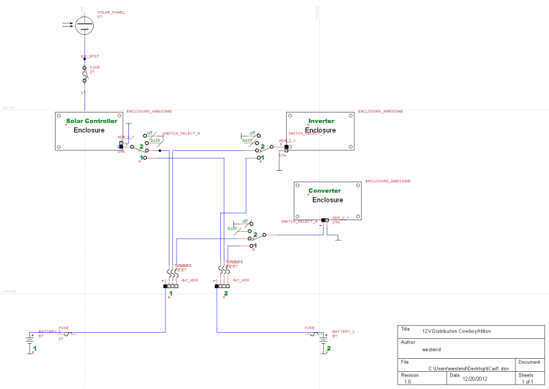
I don't have the drawing accurately depicting the grounds since I don't have them split but all running together in a box. you can see, though, how each of the three devices, the solar controller, the inverter, and the converter all have wires to both bus boxes. What I also have are three master control switches so that I can choose from which bank I connect each device. You probably won't have those switches. What you would do is pick which device is powered by which bank and connect wiring into that bus box.
Since a picture is easier to understand, I'll post some up here. That may help.
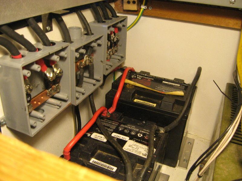
The three bus boxes located next to battery bank one:
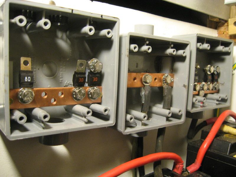
Closer image of boxes being filled. The middle box is for all (-) negative phase wires, the two battery bank bus boxes are on either side of that box.
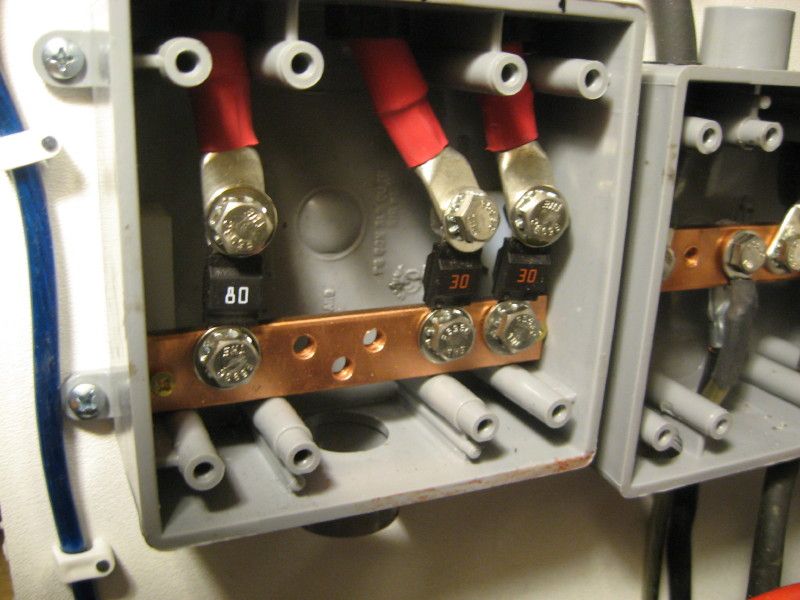
One bus box wired with the fused cables to the three devices lacking the lead to the batteries:
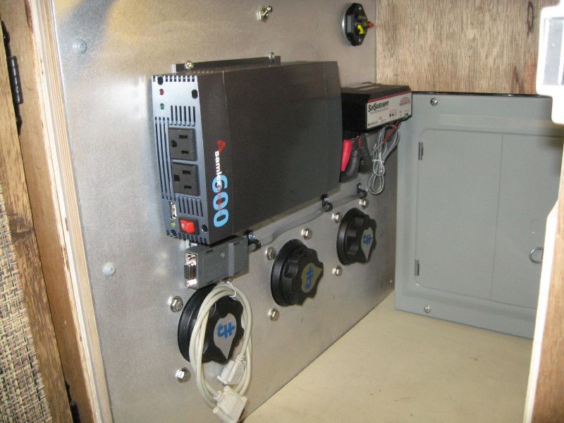
The distribution panel with the three switches and two of the three devices installed on it (the converter is located elsewhere).
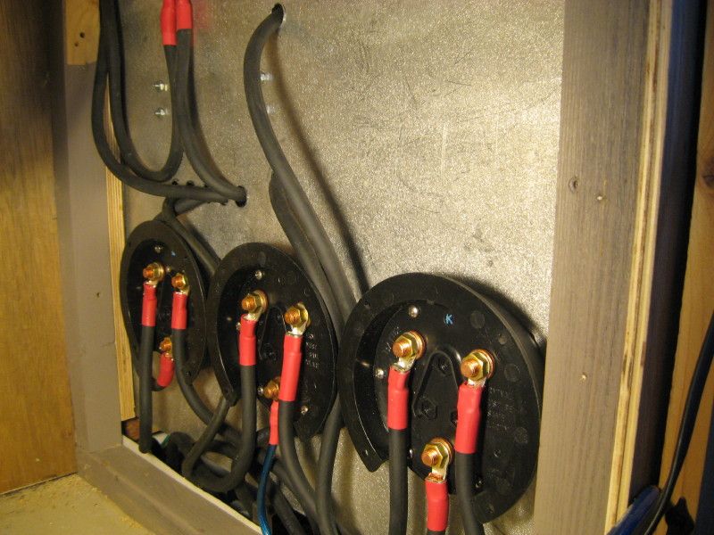
The back of the 12 V distribution board showing the cabling to the three switches:
I hope this helps to get an understanding of how a 12 V system can be laid out. You probably won't have the complications of the three switches to choose between battery banks, rather connecting directly to the three bus boxes to get power or deliver charge to the two banks of batteries. It all sounds complicated but it won't be when you have "hands on".
This way you can connect any device to any battery bank and any battery monitor shunt can be connected easily.
Here is a diagram of my 12V distribution:
I don't have the drawing accurately depicting the grounds since I don't have them split but all running together in a box. you can see, though, how each of the three devices, the solar controller, the inverter, and the converter all have wires to both bus boxes. What I also have are three master control switches so that I can choose from which bank I connect each device. You probably won't have those switches. What you would do is pick which device is powered by which bank and connect wiring into that bus box.
Since a picture is easier to understand, I'll post some up here. That may help.
The three bus boxes located next to battery bank one:
Closer image of boxes being filled. The middle box is for all (-) negative phase wires, the two battery bank bus boxes are on either side of that box.
One bus box wired with the fused cables to the three devices lacking the lead to the batteries:
The distribution panel with the three switches and two of the three devices installed on it (the converter is located elsewhere).
The back of the 12 V distribution board showing the cabling to the three switches:
I hope this helps to get an understanding of how a 12 V system can be laid out. You probably won't have the complications of the three switches to choose between battery banks, rather connecting directly to the three bus boxes to get power or deliver charge to the two banks of batteries. It all sounds complicated but it won't be when you have "hands on".
About Technical Issues
Having RV issues? Connect with others who have been in your shoes.24,397 PostsLatest Activity: Jun 28, 2026