Forum Discussion

CA_Traveler's avatar
CA_Traveler
Explorer III
Jun 20, 2015

Solar and A Brief Encounter with Leafy Shade

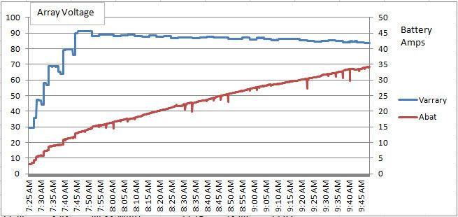
Morning solar with a tree 40’ away. 3x250W series poly panels and 3 bypass diodes per panel. Past 7:50 AM the MPPT controller is decreasing the array voltage as it seeks the maximum power from the array as the sun rises. This is indicated by the increasing battery amps.


With a 30V panel each bypass diode will bypass 20 cells or about 10V. The expanded graph shows increasing panel voltage as the tree shadows leave the panels. You can see the basic 10V increase as the bypassed panel sections comes under full sun. ie 30V, 50V, 60V, 70V, 80V and finally 90V. The voltage variations between the 10V steps are due to the MPPT controller changing the array voltage as the controller adjusts for the maximum power output. The increasing battery amps during the decreased panel voltage confirm the successful search for maximum power. Expanded graph below.


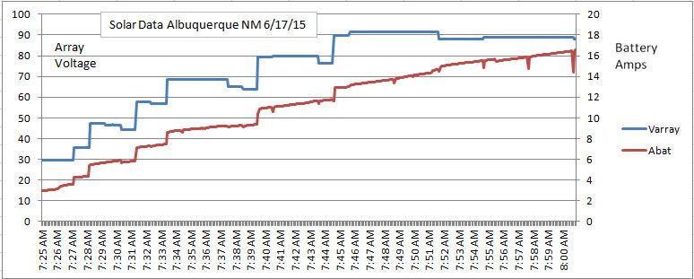
The primary purpose of bypass diodes is to protect the shaded panel from excessive heat due to the voltage from other serial panels. It’s a nice benefit that this also allows a serially connected panel to produce usable power in partial shade.

9 Replies

  • Nice plots. You can see the effects of temperature as the panel voltage decreases. From the data you can figure out actual panel temp (more or less).

    The controller is operating at the maximum power point of the array throughout the plot.
  • Always good to clarify posts. I agree that the controller is adjusting the panel load to achieve the maximum output. This information that I found by searching should help.

    A Maximum Power Point Tracking solar regulator will simulate the load required by the solar panel to achieve the maximum power from the cell. The regulator will work out at which point the cell will output the maximum power and derive from this the voltage and current outputs required for maximum power to be achieved. It will then calculate the load that it must simulate based on these voltage and current levels R=V/I. The regulator, now receiving the maximum amount of power in, will then regulate the output according to what it is designed for.

    From Wikipedia

    Solar cells have a complex relationship between temperature and total resistance that produces a non-linear output efficiency which can be analyzed based on the I-V curve. It is the purpose of the MPPT system to sample the output of the PV cells and apply the proper resistance (load) to obtain maximum power for any given environmental conditions.
  • oh i know that mppt can produce power, i know it tracks the amps the battery will absorb at a "determined" voltage level
    seeks to find the most efficient applied voltage and convert the rest of the voltage higher than that point to more amps

    BUT the controller can NOT control array resistance or affect the array in way besides presenting itself as the load (aka resistance) to absorb the power

    i do not dispute the recorded data
    only the description of the controller (controlling the array),

    more important data is the voltage being applied to batteries to achieve the amps that are being absorbed

    the panel voltage is a reflection of the "conditions" of use, solar radiance, temp, and how much energy is being fed to the controller, to be used

    what the first graph clearly shows is that as the solar radiance increases, the voltage rises, there is more power for the controller to convert to higher amps while maintaining the optimum applied voltage to the batteries

    the controller .. controls the charge to the batteries,,,NOT the solar array it self, it controls what comes out, its like a flow regulator, it can go wide open, or it can restrict, it controls what coming out, but NOT what the solar radiance does to the panel
  • Wiz,

    For a given point it time with the given sun and panel temperature MPPT seeks the maximum power from the array. This is shown on the knee of the IV curves. The controller seeks this point with less power to the left (lower voltage and higher amps) and less power to the right (higher voltage and less amps).

    Perhaps this is accomplished by adjusting the array resistance, voltage or amps. I'll see if I can find a better general explanation of how this is accomplished.

    Generally MPPT can produce about 5% more power than PWM and tends to lose that advantage with increasing panel temperature.
  • Ambient was about 70F but no temperature probe on the panels. I thought about mounting a wireless outdoor temperature sensor under the panel and do some manual temperature checking. While that might be interesting it would not be an indication of actual cell temperature.
  • Maybe I'm confused on the issue
    But I don't think the controller reduces array voltage
    Yes voltage changes, but this is because of (2) factors
    The panel warming up, and the load on the circuit
    You can only get max voltage and max amps when the sun is directly on the panels,
    The controller would love max voltage at max amps, so it could convert it to more amps
    The voltage recorded , is the voltage the panels can sustain at that temperature with the amount of solar radiation being received
  • Is there any way to plot the panel temperature along with the Vmp?
    The lower Vmp as the sun rises could be from that.

About Technical Issues

Having RV issues? Connect with others who have been in your shoes.24,277 PostsLatest Activity: Jul 01, 2025