Forum Discussion
 MrWizardModeratoryes your right it is to be avoided if possible
there is NO closer more convenient place for the controller, considering the layout of this RV
i did not want a hole all the way through the roof into the bedroom
and the Dw did not want the solar controller on the wall in the bedroom (two strikes against the shorter wire run and moving the controller
i have to live with what it is
not perfect but it works
i might raise the set point come winter time, but its high enough right now ,,there will be more Hot weather like we had for the two weeks prior to this week
this past monday was 82F, the Monday before was 101F
and the weather report says warming this week end into the 90's
today was 76f
today was great Solar weather, clear skies and a breeze to blow out pollution- MrWizard,
I hate to get off track but I think you could easily go 14.8 volt as a set point. And/or get the controller closer to the battery.
Especially considering the heavy usage.
I believe this is an example of what the OP wants to avoid. - MrWizardModeratorsun has shifted past STC and just to the west on descent
panel voltage is reading 15.78v
control volt output .. 13.85v and 19.48amps , i think the fridge is cycling - MrWizardModeratorcontroller set point is currently 14.4
currently measuring 14.04 out at 20.59 amps
input voltage is 15.71
output is being read on a turnigy power meter
input is read with a Fluke 77 at the input wiring to the controller
the controller is the xantrex C-40
the wire run to the batteries is 4ga
voltage at batteries is 13.2v yes there is drop
my battery compartment is behind the rear wheels on passenger side and exposed to the elements, batteries get very dirty
controller is in storage compartment before the rear wheels
that was close as i could get and have it accessible, did nor want it under the bedroom closet behind the drawers, and that is where the wire goes to get thru the floor to the batteries
and there are loads, this PC and 5 small 120v fans and Fantastic vent fan on low (and ol yeah the fridge cycling)
when batteries are charged/nearly charged and only the fan loads are present voltage at battery is 14.1v
these fans have been running non-stop (except for dusting) for over a month, they are on, except for cleaning, until Fall weather arrives
as a side note the system hit 31.15 peak amps yesterday, 436.3 peak watts 1624.5 wHrs
the solar weather has been great this week NOT too hot
when its too hot (like it had been) all we can do is hide in full shade and run the Generator and A/C  BFL13Explorer II
smkettner wrote:
^^^ what is missing is the controller set point assuming PWM.
I don't have a PWM set-up anymore to test with. However I do still have the manual for my old ASC controller that has a "field test" in it that may be what smk is talking about there.
"Put a solar panel in full sun. Remove any connections. The Voc needs to be 17 volts or higher to do this test.
With all ASC connections removed, connect panel + to the ASC's Array+ and panel - to the ASC's Array - (no battery connection
Measure voltage at BATT+ and BATT- terminals on the ASC. The reading should be between 14 and 15 volts (units with temp comp and adjustable set-points may vary beyond this range.
A very high reading 16-20 volts would indicate an open FET or very low reading 2-5 volt would indicate a shorted FET (open FET means will overcharge. Shorted FET will not charge a battery)
Another thing is a note I have from playing with that controller, where I had it on a battery with no array. Batt terminal v was BattV of 12.53 and there was 1.39 volts at the array terminals.- ^^^ what is missing is the controller set point assuming PWM.
- BFL13Explorer II
MrWizard wrote:
right now the sun is NOT quite STC
i am under partial shade, sun only on front panels
other panels fully or partly shaded (leafy shade NOT deep shade)
i just measured 18.88 amps @ 14.31v as controller output
input voltage measured at 15.45v
we don't know how the IP curves were created, but unless it was on a known calibrated load that we can compare too (which is not stated)
I think it was probably measured on a short circuit or directly connected to a battery
Very interesting! Would you call that 1.14 volt drop in the controller "line loss" except not in the wire paths to and from it?
The controller will have some sort of R BFL13 wrote:
Yes exactly. Amps increase to Isc causing the voltage drop along the panel IV curve.
With PWM, panel voltage = battery voltage plus line loss, so howinheck can the controller input be at 16v?
Same as any current limited charger or converter. Voltage sags anytime you are at max amps.
The issue is to have the potential to get the voltage and amps to the controller so that the wire does not create the limit but rather the battery and controller create the limits. This allows the panel to run at the maximum.
The calculation above was to present information on the needed wire so as not to cause resistance induced limits. The calculation was not intended to describe the actual voltages along the wire. red31ExplorerMy battery and panel V are the same until abs.
Panel V rises in abs cuz the meter is reading an ave of batt and VOC as the on/off duty cycle changes. Very shaded.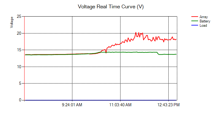
- MrWizardModeratorright now the sun is NOT quite STC
i am under partial shade, sun only on front panels
other panels fully or partly shaded (leafy shade NOT deep shade)
i just measured 18.88 amps @ 14.31v as controller output
input voltage measured at 15.45v
we don't know how the IP curves were created, but unless it was on a known calibrated load that we can compare too (which is not stated)
I think it was probably measured on a short circuit or directly connected to a battery
About Technical Issues
Having RV issues? Connect with others who have been in your shoes.24,211 PostsLatest Activity: Mar 08, 2025