Ah, now that the cross section of your latch is clearer or with more/better
detail...
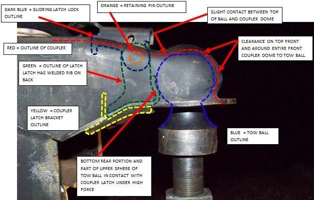
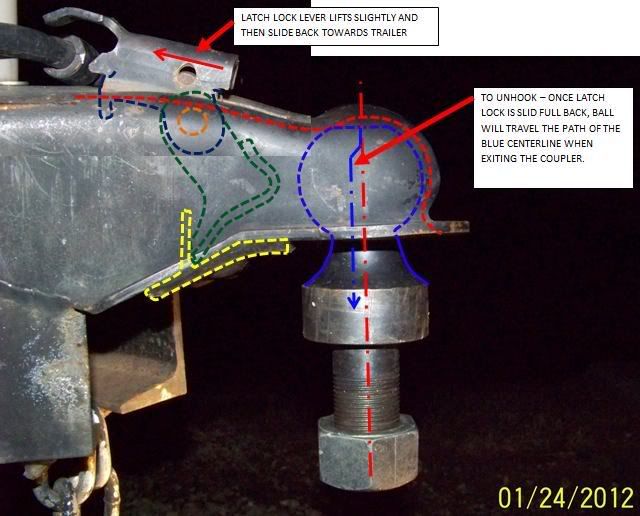
Shows that the pawl pivots on it's tail end against a bend back of
the safety plate welded beneath it.
Then the release latch mechanism uses an over center for the pawl
pivoting on it's tail end. Has to be an over center, as if not then
the ball force would lift it if the vector is above the pivot center line.
Otherwise any force from the ball would lift it against the latch
mechanism
Think that is why the latch lever has both a lift and sliding back
motion. Lift it above the over center vector line and then slide back
to get out of the way
So any force from the ball in that direction will have it see the
pawl first and get the brunt of that vector. Some will transfer up
to the latch via that food chain. The moments I can see, but the
length and other geometry would need measurement, but think small
in comparison to the vector against the pawl, then to it's tail
end against the welded safety plate
Then the questions of what is the contact area in order to figure the
PSI. Then the alloy of the steel(s), assuming both safety plate and
pawl are made of the same material alloy and same temper. Good that
the safety plate (my name, what is it called?) has been formed and
should have some work hardening. It is also a catch basin for road
grim/dirt/grit/salts/etc. Wonder how that will do with the added force
of the Andersen Hitch system?
Then the latch food chain and the PSI on the contact points, albeit
small area, small vector
There might be a compounding of vectors with the way the latch mechanism
both lifts and slides. There is a pivot rod just underneath the latch
handle.
Since an over center mechanism, wonder what kinds of shock and vectors
it will take to stay put...or jump out?
That should hopefully be mitigated by the contact between the ball and
top of the glob or as they call it the dome. That seems okay for now
as it requires the ball to drop in order to release, but again, the
latch system was never designed for this kind of dynamic loading
Will have to noodle that some more later
Plus, this is just one type of latch mechanism, wonder how the others
stack up. Think yours works best for the Andersen Hitch, as the others
use a rod/pivot and that leaves questions on how the rod is captured
on both ends, how the pawl interfaces with it, etc, etc
These images are just the ones found with a cross section, Ron's and
assume many more or at least some more designs out there.
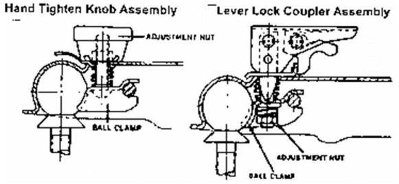
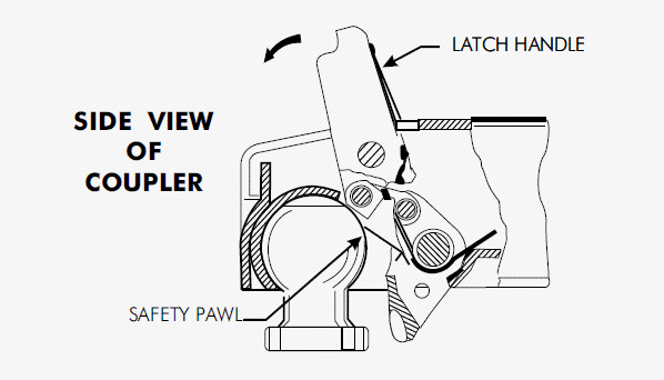
Ron's has more detail but need more on the way the rod is captured
on the pawl. Seems to be just a sheetmetal edge and that then says
all or most of the Andersen Hitch forces are focused there
{edit}
Am always forgetting that the top of the ball contacts the dome, so
not all of the forces are onto the pawl/rod, just some if it. More
so if there is tolerance allowing movement of the ball in the captured
condition...but now another new thought...how much in PSI is on that
small dome/ball contact patch?
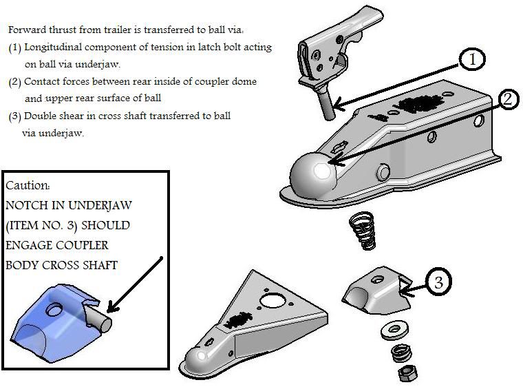
Gotta find the one Bryan posted as that one seems best suited for
this Andersen Hitch system
Moderator edit to re-size picture to forum limit of 640px maximum width to avoid scrolling.


