Forum Discussion

RoyB's avatar
RoyB
Explorer II
May 25, 2016

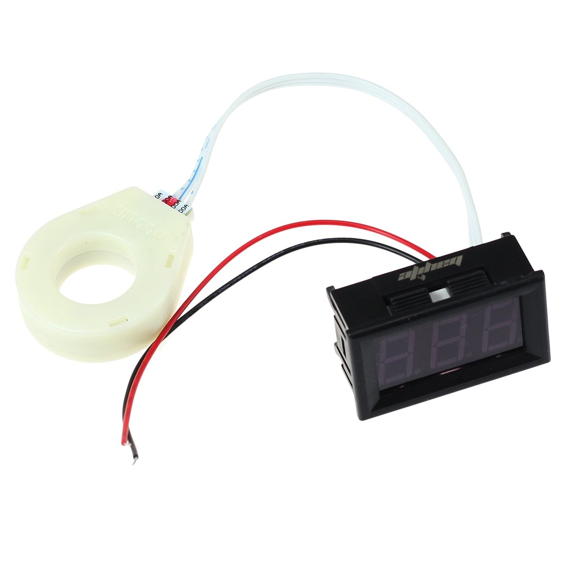
bayite DC 5-120V 100A DC Current Meter with Transformer

Was looking on AMAZON getting an oder together for my upcoming mods to my BATTERY SETUP and found this available...

bayite DC 5-120V 100A Mini Digital Current Voltage Meter with Hall Effect Sensor Transformer... Listed for $16.98


Might be worth looking into for us high Current DC MONITORING guys... No high current SHUNTS to deal with...

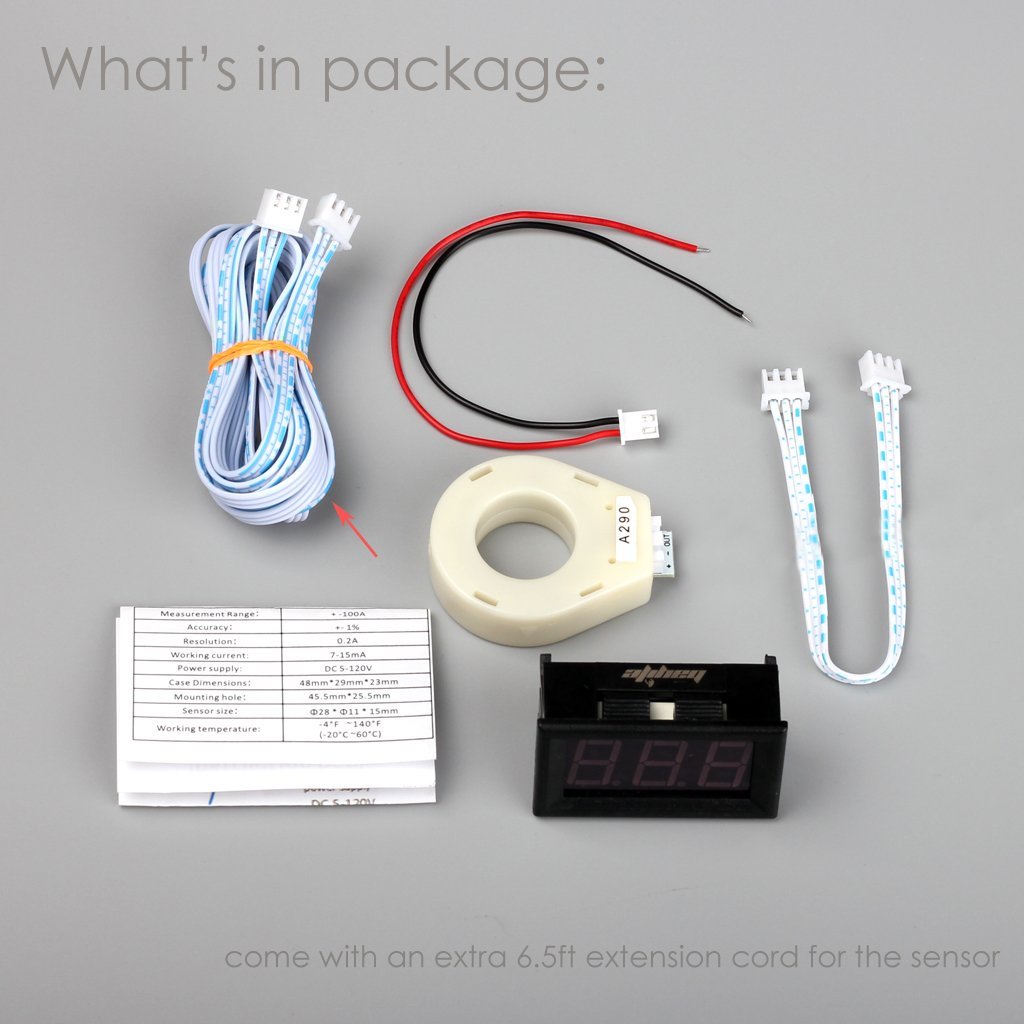
Meter size is 2.9 x 2.7 x 2.6 inches
The XMFR SAMPLE LOOP HOLE is 3/4-inch...
Includes a 6.5 foot meter cable with it as well

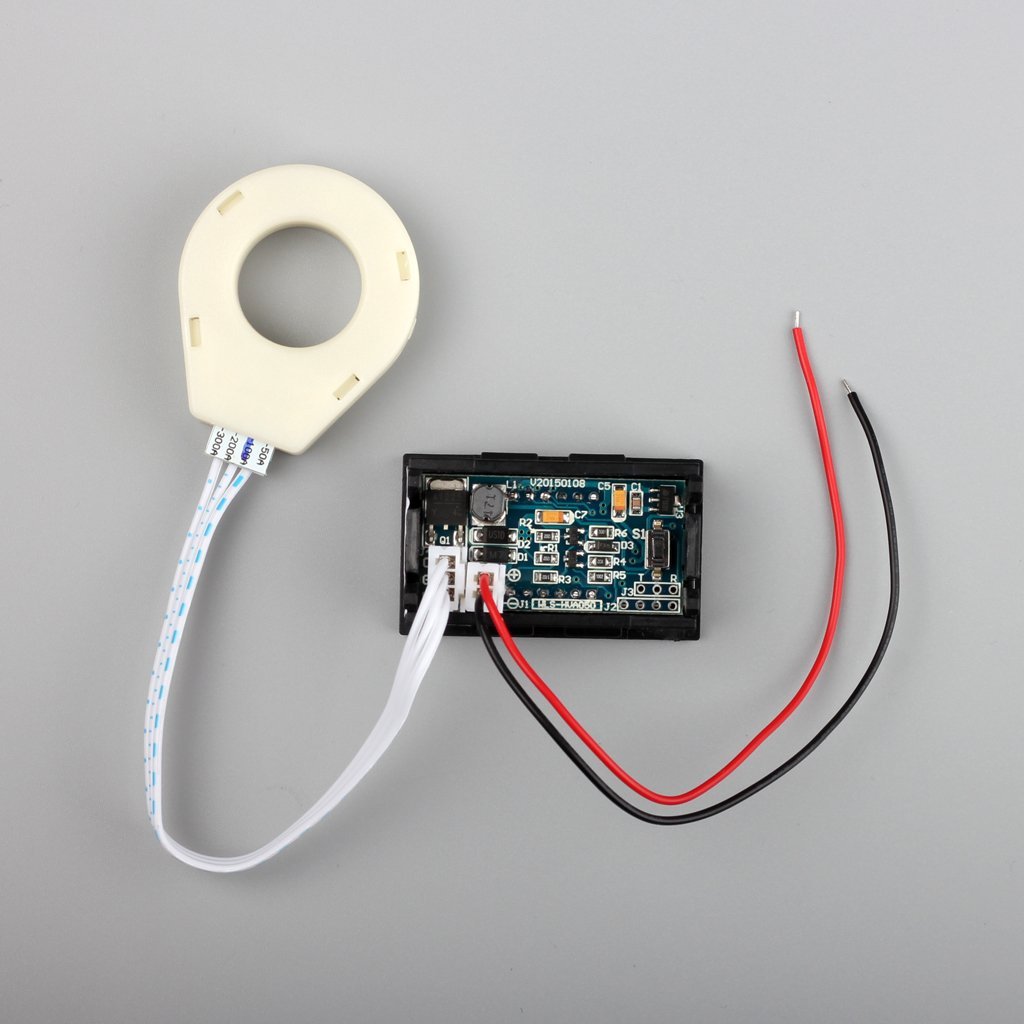
DC CURRENT 100ADC METER with XFMR


My only other requirement is to be able to measure DC current in both directions without changing wiring.. All it says in this regard is it Measures positive or negative current. No current direction limitation.

It also says it has three modes..

Three display modes:
1- alternately display Amps and Voltage
2- only display Amps
3- only display Voltage

I am definitely going to order a couple of these.


Roy Ken

23 Replies

  • Trackrig wrote:
    That's interesting and cheap enough to "Play" with.

    In the Amazon description it says: "Loop through sensor multiple times to strengthen signal. For example, if your current signal is only 0.2 Amps, you could loop the wire through the sensor 10 times and the signal would by 10X stronger and would appear as 2.0 Amps."

    To make the meter work, you have to disconnect a wire and run it through the sensor. Based on the above quote, if you have sufficient slack in a smaller wire, I wonder if you could fold it over and then stick the fold through the sensor. Since there would be two runs of the wire, you'd then have to divide the reading by two.

    Bill


    Zig-zagging or folding the wire wouldn't work because the zags cancel out the magnetic field of the zigs (and vice-versa). The gizmo measures the net current flowing through the donut. With what you describe, you have a net current of zero (since the current traveling outwards on one leg of the fold has to come back inwards on the other leg).
  • RoyB's avatar
    RoyB
    Explorer II
    In my case I will be looking at 25AMPS DC current drain with my 12VDC loads and also will want to see how much DC Current the battery bank is demanding when I am in CHARGE MODE. Hopefully I don't have to change any wiring for this...

    My OLDER XFRM Sensor does this quite easy using a MINUS symbol on the display. Hoping this one does something similar...

    My homemade DC meter panel already has two each 12VDC meters to measure the static DC Voltage on each of my two banks... I have BLUE SEA Battery switches that allows me to use one bank - both banks - OFF


    This tells me both battery banks are now showing 12.03VDC and my 12V loads are drawing a total of 18 DC AMPS... Its time for me to shut down and go into BOOST charge mode soon using my generator running my PD9260C to get my batteries back up to their 90% charge state in a three hour generator run time when I am camping off the grid.

    The reason i need more of theses is I need to do some additional DC current monitoring for some other items and of course like to play with them too hehe...

    Roy Ken
  • That's interesting and cheap enough to "Play" with.

    In the Amazon description it says: "Loop through sensor multiple times to strengthen signal. For example, if your current signal is only 0.2 Amps, you could loop the wire through the sensor 10 times and the signal would by 10X stronger and would appear as 2.0 Amps."

    To make the meter work, you have to disconnect a wire and run it through the sensor. Based on the above quote, if you have sufficient slack in a smaller wire, I wonder if you could fold it over and then stick the fold through the sensor. Since there would be two runs of the wire, you'd then have to divide the reading by two.

    Bill