Forum Discussion

gmelton2's avatar
gmelton2
Explorer
Mar 03, 2015

HELP WIRING AMP HOUR METER

There has been some discussion about these cheap eBay amp hour meters on here of late LINK. I decided to buy one and try it out. When I went to install it yesterday, there were too many wires and not enough instructions for a simple gear head like me.

This is the image for the wiring diagrams that came with the meter:


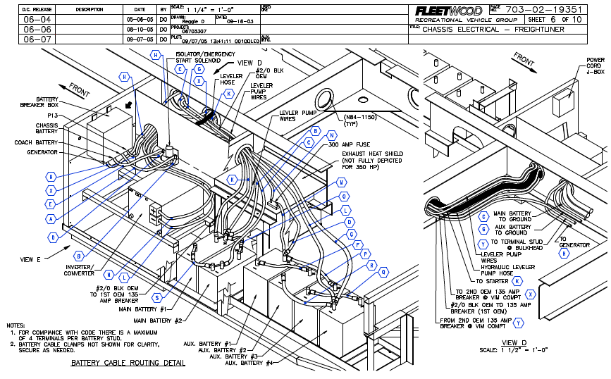
This is the battery configuration in the rear of my 2006 diesel Bounder:


I also have two additional remotely located golf cart batteries and currently have one solar panel.

It pains me to say this, but I think this is over my head. Help!!!!!
  • I'm not an electrician but...if it were me, I'd just use the wiring diagram as shown but don't hookup the green little wires. That way you would only measure the amperage from the unit while boondocking. It really isn't necessary to measure the amperage from the charging unit..converter. Thats what I do with my amp meter. Don't use any of the Elite small wires, just the large ground cable.
  • Pretty basic. The shunt is in the path to ground on the negative (-) phase. The shunt also requires connection to the blue and green wires to pass signal to the display. What is it that you're having trouble with?
  • I agree that in principle it all sounds pretty basic. And on my previous travel trailer, I had a simple in/out ampmeter installation. However, this motorhome is a level of complexity higher with the onboard generator, inverter, and then the engine altenator. There just seem to be additional cables in the back of my RV/battery compartment that in my head I can't make the leap from their diagram to my physical installation. The comment about being able to only measure when boondocking is a good one, but why go to the effort if you can't see what your onboard charger or the altenator is putting into the bank.

    A for instance question: the bonding lug to the chassis, where does that tie in the ammeter diagram?

    Thanks,

    Greg
  • I am an electrician. The shunt should be connected between the negative terminal and the two wires leaving the battery compartment on AUX 4. Make sure to leave the wire connecting AUX 4 negative to AUX 2 negative (it looks to be labeled F)

    PM me if you have any questions
  • To measure both charge and discharge current you will have to use the three wire method. You will also need an isolated DC power source to power the meter. This would connect to the first two terminals on the board. I have a similar meter and use a 9 volt wall wart to power my meter. You can also purchase an isolated DC-to-DC convertor.
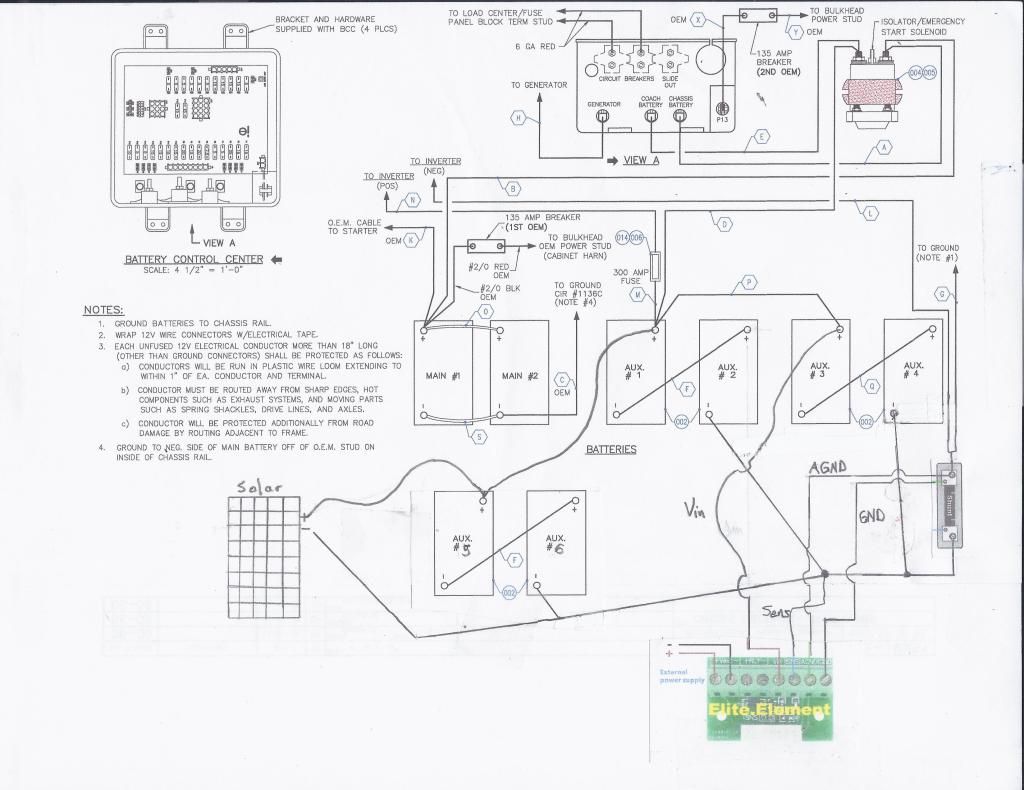
  • Well, I sat down this evening and put some thought into it and this is what I came up with. Take a look and see what you all think.

  • I doubt that a separate External power supply is needed. I have a monitor, from the same ebay dealer, I think, with that option but it was only needed if the voltage being measured was too low to operate the device. No need when it has the 12 Volt battery connected.

    If you then think of the shunt as being part of the unit (in my 20 amp unit, the shunt is inside the case), the whole thing has only three wires to connect to the outside world. Two straight to the battery and the other to the RV ground. Note that you have to disconnect the battery from ground so that all current from ground back to the battery goes through the shunt where it can be measured. I hope your unit has sufficiently heavy connectors to the shunt to handle the wires you want to use to battery negative and ground. If not, you will have to downsize the wire to a gauge that it can accommodate without breaking.

    Of course you want it to measure charging current from all sources, just as it is shown in the diagram. It can't show the state of charge without measuring the charging current. No extra wiring to accomplish that - the engine, converter and solar must already be connected to ground and battery positive.

    my monitor setup with just 3 wires coming out. Two heavy for the current and one light to power the unit and let it measure voltage.
  • I installed this meter this weekend. I have the shunt drawn backwards in my diagram. I had to flip the sense lines to get it to operate properly. The meter did function just fine when powered by the circuit.

    It seemed to be difficult to set the meter to 100% charged. While trying to set to 100%, it seemed like it adjusted 1% about every second, which seemed very slow to me.
  • Good show!
    I agree, the thing should have an easy way to set 100% charge, which users should do every time they top up the batteries.

About Technical Issues

Having RV issues? Connect with others who have been in your shoes.24,188 PostsLatest Activity: Jan 18, 2025