Forum Discussion

scootsk's avatar
scootsk
Explorer III
May 14, 2013

Help with relay wiring

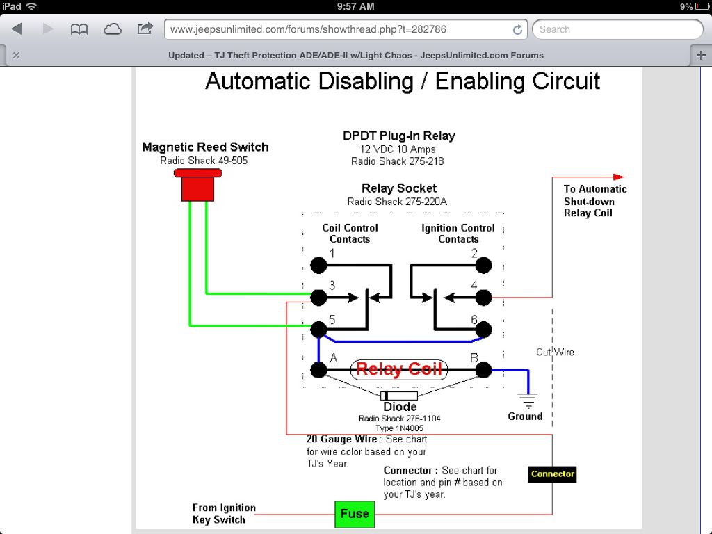
Could someone help me covert the attached wiring diagram to use a SPDT relay instead of the DPDT relay shown. I know it's possible since its only controlling one circuit.

9 Replies

  • Hamops wrote:
    I'm going to suggest that you leave the circuit exactly as it is. The circuit as designed, is protecting the reed switch. The reed switch is not intended to take any sizeable amount of current, so that's the reason for the second set of contacts. The reed switch only has to pick up the one relay coil and nothing else, which seals itself in and closes the other set of contacts that will do the work. By sealing the relay, the reed switch contacts are shorted out and not carrying any current. The relay contacts take all the current to keep the relay energized.
    From this design, there is no method to reset this circuit. Once the reed switch closes the sets the relay, the relay is energized until the main power is removed.


    Yes, the circuit is designed to reset when the power is removed, which in this case, is when the ignition is turned off.
    I know there is a way to wire this circuit using a SPDT relay but the diagram has been removed from the forum site, probably because it is archived. The commercial version of his uses a SPDT relay.
  • I'm going to suggest that you leave the circuit exactly as it is. The circuit as designed, is protecting the reed switch. The reed switch is not intended to take any sizeable amount of current, so that's the reason for the second set of contacts. The reed switch only has to pick up the one relay coil and nothing else, which seals itself in and closes the other set of contacts that will do the work. By sealing the relay, the reed switch contacts are shorted out and not carrying any current. The relay contacts take all the current to keep the relay energized.
    From this design, there is no method to reset this circuit. Once the reed switch closes the sets the relay, the relay is energized until the main power is removed.
  • Dave-Sparky wrote:
    You might think again about changing the circuit.

    As I understand the operation once the ignition is turned on a magnet is brought up to the reed switch causing the relay to latch and power the shutdown relay.

    I think the purpose for the second contacts on the output is to protect the reed switch from the inrush current of the shutdown relay. Reed switches are typically only rated for 10 to 50 milli-amps. With the current circuit the reed only has to momentarily handle the current for the latching relay, but never will see the heavier current from the shutdown relay.

    Good luck

    If you do want to try it and make the change just connect the wire on terminal #4 to #5 instead. But as noted above I would expect the reed switch to soon fail.

    Dave


    Dave

    I understand what you are saying now about the reed switch. I really don't understand a DPDT relay. I think I'm just going to use the SPDT relay with a hidden switch. Thank for pointing that out, I think you saved me a lot of aggravation.
  • scootsk wrote:
    Sorry guys, could you be more specific by telling me which wires go where for the diagram below?


    tie #85 to 30
    tie load onto 30
    tie one end of reed on 30

    tie ground to 86

    tie lead from key switch to 87
    tie other end of read to 87

    leave 87a empty

    assumptions
    relay coil is rated for 12 volt (or whatever system voltage is in use)
    Relay contacts are rated for the continuous and switching load

    That should duplicate your latching circuit.

    Good luck with the reed current

    Dave
  • Sorry guys, could you be more specific by telling me which wires go where for the diagram below?
  • Thanks for the response. The circuit is a tested circuit and the reed switch does not fail. I know this has been wired using a SPDT relay instead of the DPDT relay. I'm just looking for how to hook up the SPDT relay.
  • You might think again about changing the circuit.

    As I understand the operation once the ignition is turned on a magnet is brought up to the reed switch causing the relay to latch and power the shutdown relay.

    I think the purpose for the second contacts on the output is to protect the reed switch from the inrush current of the shutdown relay. Reed switches are typically only rated for 10 to 50 milli-amps. With the current circuit the reed only has to momentarily handle the current for the latching relay, but never will see the heavier current from the shutdown relay.

    Good luck

    If you do want to try it and make the change just connect the wire on terminal #4 to #5 instead. But as noted above I would expect the reed switch to soon fail.

    Dave

About Technical Issues

Having RV issues? Connect with others who have been in your shoes.24,354 PostsLatest Activity: Jan 24, 2026