Forum Discussion

SirBenji's avatar
SirBenji
Explorer
Jun 19, 2015

Replacement/addition of electrical

Hi folks,

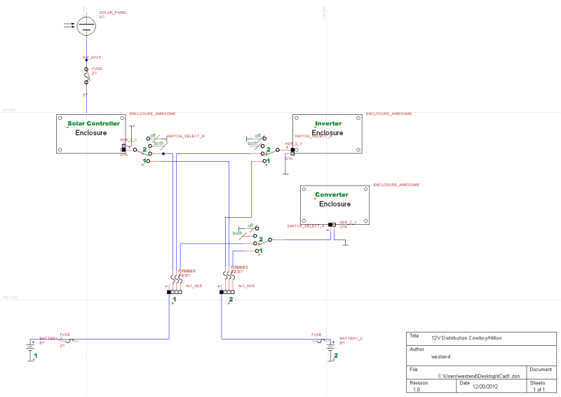
I've ordered myself a replacement converter (PowerMax PM4B-60 Amp 4-Stage Converter/Charger) and a new inverter (Samlex PST-300-12 Pure Sine Inverter). Now I need to install them both on my 1976 Coachmen Cadet Travel Trailer. There is an existing converter, but no inverter so it's not exactly plug and play.

The converter was the original with a built in DC breaker so I'll need to install an external on with the new PowerMax. I was wondering if anyone had some good wiring diagrams to help me out with what goes where? I've seen some general ones, but it would be nice to know where each positive and negative goes between my DC fuse box, AC fuse box, battery, and inverter. And of course my AC and DC loads! Both Manuals weren't much help other than reminding me how not to electrocute myself.

Thanks!!
  • SirBenji wrote:
    Okay, Ive got the inverter figured and will be setting the converter up on its own plug with switch as suggested.

    Thanks Westend. When you say distribution panel, do you mean AC or DC? My DC panel is only rated to 30A so if I put the battery and converter positives on the lead I'm worried it will be too much since I have a 60A converter. Do I need a higher rated distribution panel or did I misunderstand?
    Don't worry, the ratings for the converter are for maximum output and the DC distro panel fuse rating is about draw.
    Connect everything in parallel.
  • Okay, Ive got the inverter figured and will be setting the converter up on its own plug with switch as suggested.

    Thanks Westend. When you say distribution panel, do you mean AC or DC? My DC panel is only rated to 30A so if I put the battery and converter positives on the lead I'm worried it will be too much since I have a 60A converter. Do I need a higher rated distribution panel or did I misunderstand?
  • The only thing I'm confused about is where my 12 volt fuse panel is in relation to my coverter? In my mind I thought of is as just being a battery charger, but how do I wire it so that it can power the dc circuits without a battery? Is that where the bus bar comes in?

    In most typical converter->distribution panel connections there will be a common stud or the (+) phase wires will all be connected together. The converter is wired in parallel with the battery and distribution panel.

    If doing a new installation of the converter, I would use a terminal strip or bus bar to connect the 12 V output wire from the converter to the battery wire and the distribution panel wire. This is a pretty critical connection and you want something that won't come loose. If you have the ability to add lugs or ring terminals to the connecting wires, you could bolt them all together. Soldering and covering the connection with a waterproof junction (irrigation splice)is another alternative.

    Good luck with the converter!
  • westend wrote:
    A circuit breaker or fuse of 65 amps would be appropriate.

    In Canada, I would guess Princess Auto would be a good supplier.

    I checked Princess, it was my first stop. They had the blade fuses, but no inline fuse holders. I think I'll need to go to an electrical supply store for it. I can leave it till Monday and then throw them in before I hook it all up.

    MEXICOWANDERER wrote:
    Just took a peek at my Samlex. Too small a hole for 6awg. Eight would fit.

    Thanks for checking. I'll go with 8 then for the inverter and 6 for the converter.

    The only thing I'm confused about is where my 12 volt fuse panel is in relation to my coverter? In my mind I thought of is as just being a battery charger, but how do I wire it so that it can power the dc circuits without a battery? Is that where the bus bar comes in?

    Thanks!!
  • The fuse size will be dependent on the wire gauge as that is the primary function of circuit protection. 6AWG copper has a rated ampacity of 65Amps at 75 C and 75 amps at 90 C for the two most common jacket ratings. For your converter connection, a circuit breaker or fuse of 65 amps would be appropriate.
    I buy most of my electrical stuff at Waytek Wire since they are local and no shipping charges.

    Genuine Dealz is regarded well on the Forum for electrical supplies.

    In Canada, I would guess Princess Auto would be a good supplier.
  • Thanks West. So on the positive for the converter and the inverter I should have fuses? I have a 60amp inverter so would a 60amp fuse make sense? I'm thinking I'll run 6 guage wire on separate runs for both. About a 4 foot run. Where would love find an inline fuse of that size?
    Thanks!
  • A lot depends on the wiring layout of what you have. As a rule, inverters should be placed as close to the battery as possible. Converters should have substantial cables to connect to the battery. If you are using a converter with an included 12V distribution panel, the converter location may be at the point it was first installed and there is little other choice as DC distribution wiring needs to be taken into account.

    As a best practice, the converter cables to battery and the inverters cables to battery should be separate although using a common bus is acceptable. Both positive phase cables should have their own fuse or circuit breaker within 18" of the battery and if using a common bus, the wires from bus to device should be fused at the bus.

    You can capture a ground to frame wherever is convenient at a single ground point location.

    I'll post my system schematic but it is more complex than what you have. I have two battery banks and switches for each device (converter, inverter, solar controller) to select between battery banks. I also use common positive/negative buses. The fuse locations may shed some light.


    You only have one AC connection, the converter to 120V. It's nice to have the converter on it's own breaker and even nicer to have it plugged into a receptacle. The nicest is to have the inverter's 120V from a switched receptacle. This becomes ergonomic if you choose to power the whole trailer through the inverter (you can use the switch to close the converter charging loop).
  • So... This is what I have thus far:


    Apologies for the crude pic.

    So I know that with the DC fuses, only the positive from the battery goes into the box and then the negative just go to ground. What about for everything else? Can it just go negative to negative and positive to positive? For example, will I have 4 pos and neg lines running into my battery?

    Oh and does my diagram work or should I try something else?

About Technical Issues

Having RV issues? Connect with others who have been in your shoes.24,210 PostsLatest Activity: Mar 04, 2025