westend
Nov 04, 2014Explorer
DIY PC power supply charger
I had stumbled across this instructable article about converting a PC power supply to a multivolt power supply/charger. Since I had a few lying around, I thought I'd give it a go.
I pretty much followed the Instructable project but added a few twists, mainly the binding post panel outside the PC supply. Here's some pictures:
The Antec supply I used has two fans so I removed the top cover fan, first-
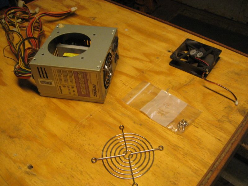
Next step is to break out all the wire lead packages and cut all the connectors off-
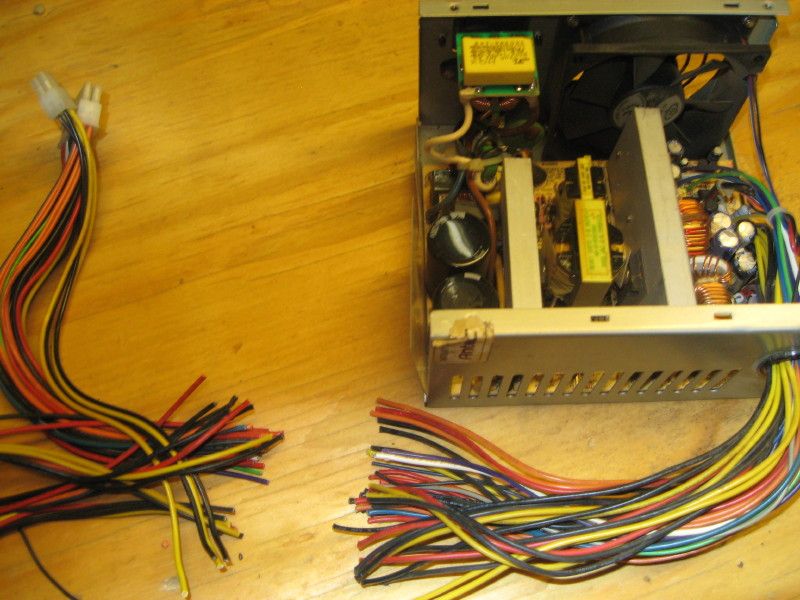
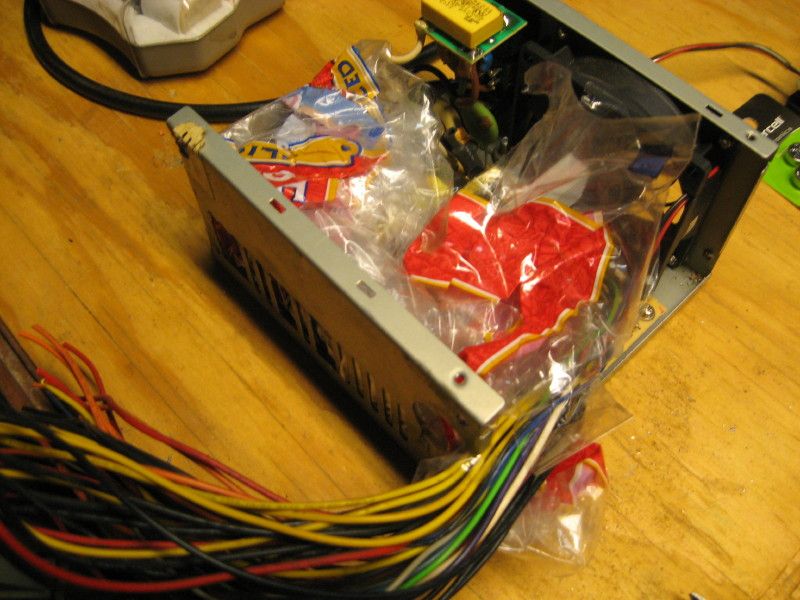
Circuit board is protected with a plastic bag while I do some dremeling and drilling-
I used a .125 aluminum panel for the binding posts where all of those cut wires are then connected-
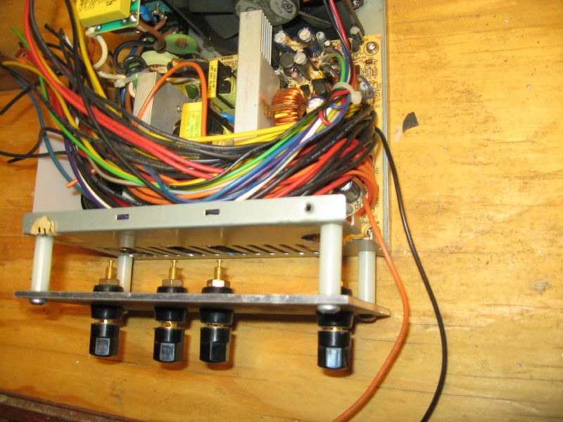
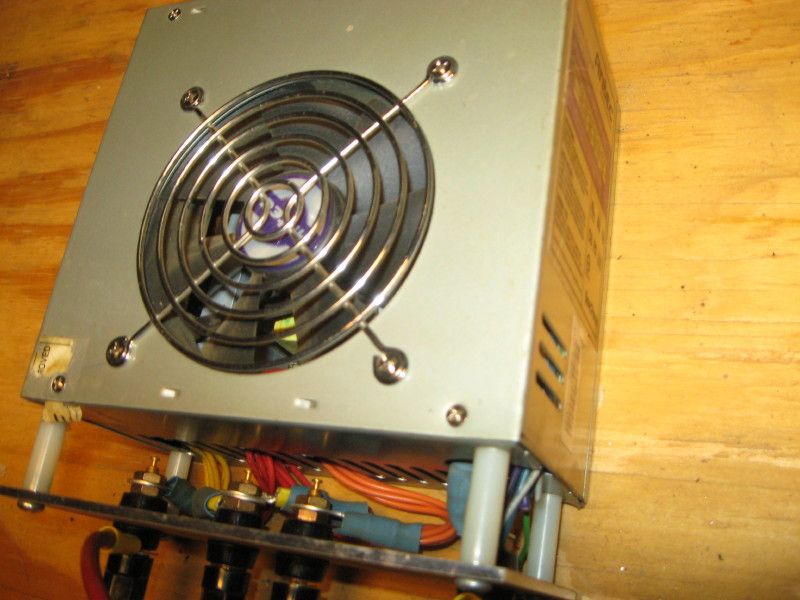
In the original article the wires are connected to the binding posts which are mounted in the original case. It was difficult to do that with a fan attached to the top cover, not much room. Here, the wires are led out of the case and attached to the binding posts-
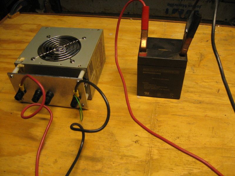
The power supply trying mightily to charge a very old SLA battery. All the voltages are spot on. If I wish to use this as a 12 volt charger or maintainer, I will either mess with the original circuits or add a DC-DC converter. In this Wiki-how article, the author reports the 12V rail capable of 23 amps. There is also the possibility to combine the -12V rail and the +5V rail to get 17V.
Like all projects like this, I was a couple of pieces short, a 330 ohm resistor to make an indicator LED, and a mini-toggle to interrupt the DC output. I swear I had those before I started, lol. Anyhow, maybe some of you have an old PC supply laying around and can put it to some use. I could have added USB slots for charging phones or may add a battery holder to charge two AA batteries. Those always seem to be in demand.
I pretty much followed the Instructable project but added a few twists, mainly the binding post panel outside the PC supply. Here's some pictures:
The Antec supply I used has two fans so I removed the top cover fan, first-

Next step is to break out all the wire lead packages and cut all the connectors off-

Circuit board is protected with a plastic bag while I do some dremeling and drilling-

I used a .125 aluminum panel for the binding posts where all of those cut wires are then connected-

In the original article the wires are connected to the binding posts which are mounted in the original case. It was difficult to do that with a fan attached to the top cover, not much room. Here, the wires are led out of the case and attached to the binding posts-

The power supply trying mightily to charge a very old SLA battery. All the voltages are spot on. If I wish to use this as a 12 volt charger or maintainer, I will either mess with the original circuits or add a DC-DC converter. In this Wiki-how article, the author reports the 12V rail capable of 23 amps. There is also the possibility to combine the -12V rail and the +5V rail to get 17V.

Like all projects like this, I was a couple of pieces short, a 330 ohm resistor to make an indicator LED, and a mini-toggle to interrupt the DC output. I swear I had those before I started, lol. Anyhow, maybe some of you have an old PC supply laying around and can put it to some use. I could have added USB slots for charging phones or may add a battery holder to charge two AA batteries. Those always seem to be in demand.