cancel
Showing results forย 
Search instead forย 
Did you mean:ย 

LandYacht Here's Your Voltage Regulator (RUSH!)

MEXICOWANDERER
Explorer
Explorer
There's (3) available on eBay.

Old TRANSPO ELECTRONICS STOCK

NOT a standard Ford regulator


See the cover phillips head screws? There's a pot underneath.

On the reverse side there is a FIFTY AMP TO-3 power transistor on a heat sink.

Inside are a couple of MR2535 avalanche rectifiers.

http://www.ebay.com/itm/Transpo-F540HD-Voltage-Regulator-FORD-1G-40-65-Amps-Heavy-Duty-/151837580701...

This is a piece of cake to use with your alternator.

If I were you I would buy one to eat now and one to save for later. This unit has been out of production AND THE EBAY PRICE IS THE SAME AS WHAT I WAS PAYING FOR THEM THIRTY YEARS AGO.
60 REPLIES 60

MEXICOWANDERER
Explorer
Explorer
Good job.

See the heatsink on the 911-02?

Oropeza, used it because he had reason to. The 7706JA and 3825JA Leece-Neville alternators that the reg was designed to field, have similar resistance to your 50/120 That means an identical field draw (amperage).

With the Transpo F540SP he took my advice and used a 50-amp rated MOSFET and a decoupler circuit that protected the voltage divider, driver transistor and power transistor in case of reversed polarity. He asked me to rig up a pair of 240 volt probes. Direct to AC. I used a 100 watt isolation transformer. He was freakin' nuts!

"If you want a bullet-proof voltage regulator, it should endure this!"

He touched probes to all terminals plus the reg case!

I connected the reg to one of my hopped-up 25SI alternators on the test bench and God Almighty, the regulator worked perfectly! Frank hired newly out of work aerospace engineers and with them came part numbers and vendors for exotic integrated circuits and power devices. When NASA was finished with a component, the vendor was more than happy to dump the remaining inventory.

I was not impressed with the 540XHD variant with the big to-3 transistor externally mounted on it's own aluminum plate heatsink on the rear.

The SP could be ID'd by it's three 32 pin IC's on the inside.

The new owners of Transpo, Wetherill Associates International, could have had China do any number of changes on any of the Transpo regulators. Yuze a guinea pig.

landyacht318
Explorer
Explorer
Thanks westend, and thanks again for that heatsink and computer fan goodie package you sent.

I'll slowly put them all to use.

westend
Explorer
Explorer
Well done Landy!
You're a credit to all DIY'ers, the results speak volumes.
'03 F-250 4x4 CC
'71 Starcraft Wanderstar -- The Cowboy/Hilton

landyacht318
Explorer
Explorer
Buttoned everything back up after another test at idle. In that test I felt the backside of the transpo VR. It was warm, so I cut up a finned heatsink that westend mailed me over a year ago, and thermal epoxied it to the backside.


Each full turn of the potentiometer yields a 0.3v change.

At 8.5 of 10, the voltage is 14.9v so I assume max voltage will be about 15.35v.

When the engine is hot, at Idle in gear at 525 rpm, voltage slowly sags from 14.4 to 14.1v. This is with a battery requiring 24 amps to be held at 14.4v. I previously measured 8.2 amps current required just to idle the engine, so ~32.2 amps total output. Slight rpm increases and voltage goes back upto 14.4v, not quite instantly though.

Twisting the Dial upward, at hot idle when voltage sags, is effective. But when I kept bumping it upward, to 14.7v at hot Idle, then the check engine light came on.

When I parked I checked computer codes via the 'key dance' Code 46 was present.

Bob Oโ€™Neill and Bob Lincoln wrote:
Code 46 is triggered when the voltage sense input is more than one volt above the target voltage for 20 seconds, as sensed by the computer. When code 46 is triggered the power limited light will be lit and the system will not enter limp mode. When the charging voltage falls below one volt of the target voltage the power limited light will go out but the code will still be stored.


whether the above quote is 100% accurate to my Van is ...unlikely. But the light came on at 14.7v and 13.7 was a favorite setpoint of the ECM's VR.

After checking codes I restarted engine with Pot set to 7.0/14.4v and the check engine light went out after starting and has remained off since.

Parking for the night and continuing to idle, the VR's backside, the black heatsink measured 127f via my IR temp gun and the whole casing was warm. Perhaps a 60mm fan that comes on with engine running might be beneficial.

When engine coolant and engine oil were at normal temps, The alternator was 119f, and this rose to 140f as I continued to idle, testing, with battery still requiring ~20 amps to be held at 14.4v and the ~8.2 amp draw required to run engine. So Idling significantly increased alternator temperature compared to moving.

At Hot idle, field current was 2.63 amps for 28 amps total alternator output at 14.4v. Revving the engine to 2k rpm max and field current dropped to the 1.3 amp range. The more loads I turned on, the more field current was required.
With high beams, fog lights, and blower motor on high, the max amps I saw was 8.23 at idle, revving the engine and field current dropped by half.

The 'S' terminal for the switched 12v+, that wire only registers as passing 0.02 amps at idle. Guess the 14 awg I used to trigger it was a few thousand degrees of overkill. Wish I tested that before running that nice 14awg yellow wire to it.

The 10 Ohm resistor thermal epoxied to the larger heatsink maxed out at 127f idling cold and warming up a full 100 degree F drop from previous test without extra heatsink, engine cover off, mechanical engine fan barely turning. The black part of the heatsink furthest away measured 125.5f so it appears the resistor/thermal epoxy heat transfer is pretty efficient.

I started the engine with 13.2v setpoint, which is was the solar was able to maintain on its own at the time, so the alternator load was practically nothing, the engine note was nice and smooth.

When bumping voltage upward to 14.7 and ~32 amps were required to get battery to 14.7v, engine note changed noticeably with the extra load of the alternator producing 40+ amps and responded in kind when I lowered voltage back to 13.2v for basically zero alternator output.

A better test will be a battery depleted enough that it requires 60+ amps to achieve 14.4v..

I put the Bourns counting potentiometer on my gauge cowling.


So Mission Accomplished. My ECM's whack job of a Voltage regulator has been bypassed in such a way that the check engine does not illuminate if voltage is not allowed to exceed ~14.7, at least at idle.. I have a high Quality Bourne's 10 turn potentiometer on my Dashboard allowing me to choose any voltage ranges from at least 13.2 to 15.3v, thus allowing me total control of alternator output, within its capabilities at rpm.

Temperature data of the alternator casing at different output levels and different speeds should be interesting.

Consider the Jig, danced.
So far the experiment is a success.

landyacht318
Explorer
Explorer
I just erased my RV.net bookmark and replaced it with Woodall's, I got sick of being denied of the ability to post.


Hey Mex, what's your opinion on this TransPo F540XHD?

Notes:
Terminal identification: I Light, A B+, S Stator, F Field, Case B-.
Extra heavy duty version of F540S-1

Features:
Extra Heavy Duty
Short circuit protected
Load dump protected
30 amp power device
Adjustable voltage

Reference No. F540XHD


http://store.alternatorparts.com/partnof540xhdfordoed9pz-10316-ae2pz-10316-af0az-10316-af0pz-10316-a...

This trick the ECM resistor was getting quite hot during the test with a fully charged battery and a sub 2 amp field current. Me wonders if something in the ECM is also getting ridiculously hot where before it was not.

Me wonders if there is a better way to 'trick the ECM' effectively

I did run the engine with nothing attached at all to molded connector field terminals and the CEL light did not come on in the minute or two It idled but the battery was holding 12.8+ volts still.

My engine requires 8.2 amps at idle.

This adjustable regulator will allow me to take almost all alternator load off a freshly started cold engine, instead of my old VR instantly seeking 14.9 and causing the alternator to goto max output.

MOre data to come.

landyacht318
Explorer
Explorer
As if a 3600 degree potentiometer on the dashboard to control voltage is not overkill enough, Overkill can take many forms.

This is a standard Home Despot 10-12awg ring terminal with the yellow nylon/plastic insulation removed. I decided to try and get some insulation inside the crimp since there was some room with 12awg. I tapered the insulation so it would fit.


Really digging the 'amazing goop', here used as strain relief on the Pot solder connections. The white portion is where the goop when over the masking tape. I can cut that off cleanly.


This is a '6'awg die crimp on my HFT hydraulic crimper, the first model with the black undersized dies. It is Just a little too small for a 10-12 crimp.


Amazing how much more comfortable I am with soldering now compared to a year ago.


Before crimping, copper stranding and ring terminal cleaned with 91% IPA. Base of wires next to insulation got a drop of DeOxit shield. then crimped, cleaned again and soldered to cover the stranding.

-10awg goes the few inches from one alternator field terminal to ground
12awg for the battery + always on. Wired this to AlT(+) stud
12awg for fieldwire, wired to one alternator field wire terminal.
10awg for ground from transpo540HD to alternator ground stud
A 6 foot long K type thermocouple is run inside the new Vr harness and sensor tip is thermal epoxied to the Stator exterior prepped and degreased beforehand.
A 14 awg switched lead runs back to a factory switched hot. It is Only on with engine running, not with ignition turned to just 'on'.

The rather extreme temperature of the 'trick the ECM resistor' is dismaying. I wonder if something inside my engine computer is now getting significantly hotter because of it.

I thermal epoxied it to a larger aluminum finned Heatsink that Westend sent me a while back.


The 12 awg runs from resistor, about 10 inches to the molded connectors field terminals
The red electrical tape below resistor is the Feed to the 30 amp 1/2/both/off battery switch common stud in back. Plenty of chafe protection on resistor wires where they contact heatsink.

landyacht318
Explorer
Explorer
Drum roll please......


..
.
.
..

...
.
.
.
.


.


.
.
''
'
'
'
'

''
'
'
'


It works. No check engine light. Whohoo!!!!!
Voltage range I checked from 13.2 to 14.9 with a full charged battery.

Field current 1.2 to 1.8 amps

The resistor got hot, 214F on the hottest spot

Now to make it permanent an clean since the test was a success.

Buhahwahahhahhhahaaaa.
Thanks Mex

landyacht318
Explorer
Explorer
The molded connector field terminal tabs are more than 1/4 inch thick, the next size up quick connects are loose and wobble. Even if squeezed with pliers I can pull them off all too easily.

I want to be able to return the OEM VR to duty easily if I have to, So ring terminals it will be.

I saved some threaded brass contact and screw from a Switch I wore out. It has a nice wide flathead brass screw and will hold ring terminal to Connector tangs nicely.

I will use some wire insulation over the field terminal studs preventing accidental contact.

Guess I should get to it rather than type on this **** laptop

MEXICOWANDERER
Explorer
Explorer
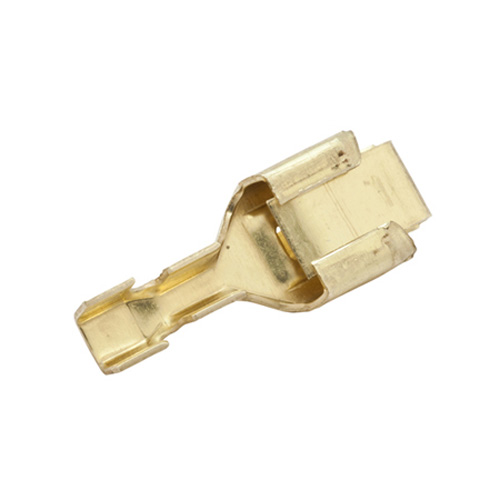
Packard type Fast-On terminals would have been preferable for the reg tang connections.


http://www.delcity.net/images/photos/925725_primary.jpg

Lay a neatly trimmed (painted black) Popsicle Stick across the fast-ons that have been sheathed in dual wall heat shrink tubing. Coat top and bottom with GOOP. You can additionally help things by connecting a .47uf 100 volt electrolytic cap from the reg A terminal to negative and connect a freewheeling diode biased reverse from neg to the reg F terminal.

landyacht318
Explorer
Explorer


Was able to just get molded connector field terminal tabs out of the way and reattach connector. will attach trick the ecm resistor to these tabs with ring terminals for today's test.

Have to go through woodalls portal to post.

landyacht318
Explorer
Explorer
.


Wire soldered to trim pot legs, twisted tightly, sheathed, run through a ferrite ring, and 'amazing goop'ed to flats.

I could swing VR by Pot leads like a weapon

MEXICOWANDERER
Explorer
Explorer
"The California Highway Patrol accident report stated the driver admitted to taking his eyes off the road 'for a moment' just before the vehicle plunged over an overpass railing and dropped through the roof of a Liquor Barn, with the front bumper smashing 6 cases of vintage Chateau Haut Brion french wine"

I can just see it now...

landyacht318
Explorer
Explorer
Other projects took precedence this week so I only pulled out the transpo f540hd today.

I practiced the wood Dowel holding the ring terminal trick on a set of clamps from a old retired small jumper pack that came with a 12AH Asian AGM battery, now long recycled. Only one of the jaws was live so I ran 10awg to the other Jaw of the same clamp:


This is 10 awg in a 10-12 ring terminal, crimped in the hydraulic crimper. The die size was not perfect, note the thin ears:


I angled the ring terminal and wire up towards the the other output wires, which are just temporary in this photo. I did heat shrink the terminal for the idiot light with blue, and I half covered the bases of the other terminals with yellow heat shrink as I am just going to run individual insulated quick connects to these terminals rather than get the red ford Connector. I am going to mount this inside the Van on the firewall. Got a great spot for it that will keep the run to the alternator under 3.5 feet long, and well protected.

It soldered pretty well with butane torch and 140 watt gun. I covered all that exposed copper stranding. Forgot to take a pic tonight.

I was able to pull the little plastic ring from the potting material under the potentiometer, and then use the dremel to remove enough potting to get at the 3 potentiometer legs:


The two legs on the right are electrically the same. Between those two and the other leg on the left I measured 748ohms. I snipped them off leaving about 3 to 4mm to solder wires to for the external pot.

I got tired, and did not solder wires to the them.I need to find a nice small grommet for where the wires will enter the cover.

Mex, the 12v+ always on/voltage sense wire....If I were to run a separate wire to the battery, does this wire carry much current? Can it be 22 awg?

I plan on 12awg for the 12v+ ignition switched on and for the Field terminal, and 10awg for the one field terminal to alternator casing, and the ground from transpo casing to Alternator casing is 10awg.

Looking forward to dialing a voltage when driving. If it all works.

landyacht318
Explorer
Explorer
Heck I'll mostly be using this at 14.4v to tame the wild swings from 13.6 to 14.9 that my mopar voltage regulator currently decides to play with, at random, devoid of any logic.

If I know the battery is full then I'd only allow 13.8v, depending on what my battery temperature probe reads.

Not sure how many twists will be needed to go from 14.4 to 13.8, but will let you know.