cancel
Showing results forย 
Search instead forย 
Did you mean:ย 

Replacing my Converter/Charger - Help

Steve92004
Explorer
Explorer
Hi Guys/Gals
I have a 25' Weekend Warrior toy hauler and last week in Baja my my Iota DSL-30 converter/charger stopped working
I bought a PowerMax PM4 100A converter/charger to replace it
I was thinking about just putting it in the same spot as the old converter/charger but I started reading around and most said to move it closer to the battery.
It got kind of confusing on how to do that, they said to run power from the breaker that supplies the converter to the new location and use the existing wires to run the power back to the fuse box
I don't get that part
I'm also going to be replacing my one 12v Deep Cycle with two 6 Volt deep cycle batteries, that part makes sense to me
Could somebody help clarify the moving of the converter or if it's just ok to replace the old one in the same place
Thanks!

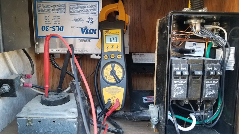
Here's a picture of what I have, sorry for the multimeter in the way, I took the photo when I was trouble shooting the problem
64 REPLIES 64

DrewE
Explorer II
Explorer II
Steve92004 wrote:

I turned it up all the way and it's at 16.6V
The instructions say it should stay at the set level for a half hour and the decrease and stay at that level for two hours, and then decrease to float level

I thought smart chargers were supposed to work on voltage not timing

Edit.... It dropped to 15.8 after 30 minutes


They can't work on changing voltage while supplying a fixed voltage. All the unit will ever see when set at 16.6 V is 16.6 V (assuming it can supply enough power to maintain that voltage level, of course).

What it could theoretically do is monitor current and drop based on reduced current, but house loads would mess that up unless it sensed the battery current rather than its output current. Alternately, it could turn off the charging momentarily every now and then and see what voltage the system is resting at, which would lead to flickering/flashing lights and probably not be any too accurate due to surface charge on the battery.

Without actual battery instrumentation to more accurately monitor its state of charge based on usage, resting voltage, etc., a timer setup in combination with some rough voltage and current triggers is probably about as good as can be reasonably done by an RV converter.

BFL13
Explorer II
Explorer II
"I turned it up all the way and it's at 16.6V
The instructions say it should stay at the set level for a half hour and the decrease and stay at that level for two hours, and then decrease to float level

I thought smart chargers were supposed to work on voltage not timing"

The "three-stage" charging profile is what you are looking at there. I think. That was showing in your earlier photo. If this is in a different part of the manual, I can't say. I don't have a copy of that manual.

When it is switched to single and the pot is twiddled to a chosen voltage, it should stay at that voltage forever (unless it drops one volt after the half hour is up---we'll see) The old ones dropped a volt after 15 minutes and then stayed at that forever, so you have to adjust the voltage again after the 15 minutes to get what you want.

PM sells mostly to car showroom folks and that's what they want. ( I guess it simulates what alternators do by dropping voltage soon after you start the car) It is a nuisance for RVers though (5% of the customers? )--but we have to take what we can get! ๐Ÿ™‚
1. 1991 Oakland 28DB Class C
on Ford E350-460-7.5 Gas EFI
Photo in Profile
2. 1991 Bighorn 9.5ft Truck Camper on 2003 Chev 2500HD 6.0 Gas
See Profile for Electronic set-ups for 1. and 2.

Steve92004
Explorer
Explorer
Steve92004 wrote:
BFL13 wrote:
EDIT--yes, turn it up as high as it goes --16.5 say, and leave it there doing nothing. After half an hour it might suddenly drop by itself to 15.5. (like the old ones do after their 15 minutes) The test is complete after say an hour and hope it is still at 16.5.
-----------

If you leave the frame as the neg path and run a length of #4 as the pos, that would be fine. You expect 75 or so amps so IMO use a 100 amp ANL fuse near the pos battery post. There might be a 40amp (approx.) DC circuit breaker there now from before. Keep that in the pos line going from battery to fuse panel to continue to protect that wire.

If you have the wire, you can improve things a lot by also running #4 from converter to battery on the neg side, paralleling the neg path via the frame. This will reduce the R of the neg path, better than just the frame or just the #4. ( You don't need the pos and neg to be the same R because it is the whole circuit's R that matters, so just reducing the neg part counts for total R reduction. In fact any reduction in R on either path counts to the good.

Leave some slack in your neg wires to the battery. Eventually you will get a Trimetric with its shunt that has to go somewhere, and you will need the slack to reach the shunt. ( All the neg wires (including the wire that now goes from the frame to the neg battery post) then go the shunt, and only one (fat) neg wire then goes from the shunt to the battery.)


Thanks!
I'm going into town tomorrow for Mother's Day and I'll pick up some #4 CU and get this thing done


I turned it up all the way and it's at 16.6V
The instructions say it should stay at the set level for a half hour and the decrease and stay at that level for two hours, and then decrease to float level

I thought smart chargers were supposed to work on voltage not timing

Edit.... It dropped to 15.8 after 30 minutes

Steve92004
Explorer
Explorer
BFL13 wrote:
EDIT--yes, turn it up as high as it goes --16.5 say, and leave it there doing nothing. After half an hour it might suddenly drop by itself to 15.5. (like the old ones do after their 15 minutes) The test is complete after say an hour and hope it is still at 16.5.
-----------

If you leave the frame as the neg path and run a length of #4 as the pos, that would be fine. You expect 75 or so amps so IMO use a 100 amp ANL fuse near the pos battery post. There might be a 40amp (approx.) DC circuit breaker there now from before. Keep that in the pos line going from battery to fuse panel to continue to protect that wire.

If you have the wire, you can improve things a lot by also running #4 from converter to battery on the neg side, paralleling the neg path via the frame. This will reduce the R of the neg path, better than just the frame or just the #4. ( You don't need the pos and neg to be the same R because it is the whole circuit's R that matters, so just reducing the neg part counts for total R reduction. In fact any reduction in R on either path counts to the good.

Leave some slack in your neg wires to the battery. Eventually you will get a Trimetric with its shunt that has to go somewhere, and you will need the slack to reach the shunt. ( All the neg wires (including the wire that now goes from the frame to the neg battery post) then go the shunt, and only one (fat) neg wire then goes from the shunt to the battery.)


Thanks!
I'm going into town tomorrow for Mother's Day and I'll pick up some #4 CU and get this thing done

BFL13
Explorer II
Explorer II
EDIT--yes, turn it up as high as it goes --16.5 say, and leave it there doing nothing. After half an hour it might suddenly drop by itself to 15.5. (like the old ones do after their 15 minutes) The test is complete after say an hour and hope it is still at 16.5.
-----------

If you leave the frame as the neg path and run a length of #4 as the pos, that would be fine. You expect 75 or so amps so IMO use a 100 amp ANL fuse near the pos battery post. There might be a 40amp (approx.) DC circuit breaker there now from before. Keep that in the pos line going from battery to fuse panel to continue to protect that wire.

If you have the wire, you can improve things a lot by also running #4 from converter to battery on the neg side, paralleling the neg path via the frame. This will reduce the R of the neg path, better than just the frame or just the #4. ( You don't need the pos and neg to be the same R because it is the whole circuit's R that matters, so just reducing the neg part counts for total R reduction. In fact any reduction in R on either path counts to the good.

Leave some slack in your neg wires to the battery. Eventually you will get a Trimetric with its shunt that has to go somewhere, and you will need the slack to reach the shunt. ( All the neg wires (including the wire that now goes from the frame to the neg battery post) then go the shunt, and only one (fat) neg wire then goes from the shunt to the battery.)
1. 1991 Oakland 28DB Class C
on Ford E350-460-7.5 Gas EFI
Photo in Profile
2. 1991 Bighorn 9.5ft Truck Camper on 2003 Chev 2500HD 6.0 Gas
See Profile for Electronic set-ups for 1. and 2.

Steve92004
Explorer
Explorer
BFL13 wrote:
What a deal! $150 and free shipping for an adjustable 75 that will also do auto three stage. ๐Ÿ™‚

If you can, please try your voltmeter in the DC terminals, set it to single and twiddle the voltage pot through its range. Yours says 16.5, but some actually do 15.5 as the max. It would be significant if these do 16.5 for real so you can equalize with them too. If it only does 15.5 then they have a typo on it.

One thing might be where in the three stage mode it does the 14.6 for half an hour then drops to 13.6. On the old models, that was only for 15 minutes every time but would stay longer at 14.6 with a lower battery that needed longer to recharge. But that also had an effect on the adjustable setting, where you can set it as high as 16.5, but then it drops a volt after 15 minutes to 15.5. So if you set 14.8 at first, it would drop to 13.8 after 15 minutes then you had to crank it back to 14.8 and now it would stay there.

I am wondering if this one will drop a volt from the first setting but now after half an hour instead of 15 minutes. Easy to deal with if it does, but it would be better if it would just stay at the first setting and that first setting could be as high as 16.6 instead of just 15.5, which is too low for equalizing. I hope that it does stay at the first setting with a range to 16.5. Might not.

So, if you have half an hour to spare testing for that, please let us know what it does.


I plugged the converter in and with no load it's doing 14.7
You want me to just turn it up using the pot and no load and see how high it goes?

Steve92004
Explorer
Explorer
BFL13 wrote:
Steve92004 wrote:
I have a question, if I put that 75 amp in the same spot as the old 30 amp with 15' of cable each way, what size cable would I need for it to work?


I was running some tests so you caught me at a good time to check that.

I have a PM3-75ADJ so same thing as yours for this part. I used my Honda 3000 to run it about 125v input. I put the trailer on whole house inverter and ran a kettle, showing minus 89 amps on the Trimetric. I used about 30 ft of #2 copper-aluminum jumper cable (that is two wires each 30 ft) and plugged in the 75 amper set to 14.8 volts.

Trimetric amps went back to minus 8 amps so that means the 75 was doing 81 amps, which is not crazy. Most of these converters will do more than their rated amps in that kind of set-up. On actual battery charging they have to work harder and do more like their rated amps or a tad over.

So--what is needed for 15 ft distance to get the 75 amps? I am thinking you could do it with #4 copper (not cu-al) based on that test I just did.

On that, instead of going fatter wire for more money, what would it matter if you used #4 cu and it only did 70 amps? That is plenty on a pair of 6s.


That's what I was thinking
The original is using the frame for the negative connection with just a jumper between the converter and the frame and another jumper between the negative battery terminal and the frame.
So that's less distance if I go the same route
I'm guessing I need a fuse somewhere close to the battery also right?
I spent half the day just cleaning up the rust, repainting, and mounting the new boxes


BFL13
Explorer II
Explorer II
Steve92004 wrote:
I have a question, if I put that 75 amp in the same spot as the old 30 amp with 15' of cable each way, what size cable would I need for it to work?


I was running some tests so you caught me at a good time to check that.

I have a PM3-75ADJ so same thing as yours for this part. I used my Honda 3000 to run it about 125v input. I put the trailer on whole house inverter and ran a kettle, showing minus 89 amps on the Trimetric. I used about 30 ft of #2 copper-aluminum jumper cable (that is two wires each 30 ft) and plugged in the 75 amper set to 14.8 volts.

Trimetric amps went back to minus 8 amps so that means the 75 was doing 81 amps, which is not crazy. Most of these converters will do more than their rated amps in that kind of set-up. On actual battery charging they have to work harder and do more like their rated amps or a tad over.

So--what is needed for 15 ft distance to get the 75 amps? I am thinking you could do it with #4 copper (not cu-al) based on that test I just did.

On that, instead of going fatter wire for more money, what would it matter if you used #4 cu and it only did 70 amps? That is plenty on a pair of 6s.
1. 1991 Oakland 28DB Class C
on Ford E350-460-7.5 Gas EFI
Photo in Profile
2. 1991 Bighorn 9.5ft Truck Camper on 2003 Chev 2500HD 6.0 Gas
See Profile for Electronic set-ups for 1. and 2.

Steve92004
Explorer
Explorer
I have a question, if I put that 75 amp in the same spot as the old 30 amp with 15' of cable each way, what size cable would I need for it to work?

BFL13
Explorer II
Explorer II
The new converter draws way more watts of 120 than your little 30 amper, so sharing with the fridge and kitchen GFI (for kettle. toaster) would likely be popping the breaker too often.

If you ever get into running the 120v stuff on whole house inverter (shore power plugged into your inverter), then you have to shut off the converter(s) so being able to just unplug the 75 is good when sharing it with receptacles so the receptacles stay live. You don't want to use the shared CB as the switch to turn off the converter and then also kill the receptacles.

The Iota would also need to be turned off when on whole house inverter, so if it does not just unplug, that is awkward. Of course if the Iota got fried you can just snip its 120.

If it fits you could swap out that single 15 for a double 15 and have another "branch" - ISTR there is a rule to just have the four branches for that size panel???? but who is going to inspect your rig anyway ๐Ÿ™‚

EDIT--if your Iota still works as your shore power converter, then the only time you would use the 75 is from the generator. If you can plug the converter into the gen directly (via extension cord, by-passing the main 120 panel), you don't really need to run a new 120 receptacle up by the 75.
1. 1991 Oakland 28DB Class C
on Ford E350-460-7.5 Gas EFI
Photo in Profile
2. 1991 Bighorn 9.5ft Truck Camper on 2003 Chev 2500HD 6.0 Gas
See Profile for Electronic set-ups for 1. and 2.

Steve92004
Explorer
Explorer
BFL13 wrote:
What a deal! $150 and free shipping for an adjustable 75 that will also do auto three stage. ๐Ÿ™‚

If you can, please try your voltmeter in the DC terminals, set it to single and twiddle the voltage pot through its range. Yours says 16.5, but some actually do 15.5 as the max. It would be significant if these do 16.5 for real so you can equalize with them too. If it only does 15.5 then they have a typo on it.

One thing might be where in the three stage mode it does the 14.6 for half an hour then drops to 13.6. On the old models, that was only for 15 minutes every time but would stay longer at 14.6 with a lower battery that needed longer to recharge. But that also had an effect on the adjustable setting, where you can set it as high as 16.5, but then it drops a volt after 15 minutes to 15.5. So if you set 14.8 at first, it would drop to 13.8 after 15 minutes then you had to crank it back to 14.8 and now it would stay there.

I am wondering if this one will drop a volt from the first setting but now after half an hour instead of 15 minutes. Easy to deal with if it does, but it would be better if it would just stay at the first setting and that first setting could be as high as 16.6 instead of just 15.5, which is too low for equalizing. I hope that it does stay at the first setting with a range to 16.5. Might not.

So, if you have half an hour to spare testing for that, please let us know what it does.


Sure thing, I'll check that out tonight and see what it does
It looks like the power converter shares the same circuit with the Fridge and Kitchen GFI outlet,
I wonder if I should run a new circuit from breaker that does the rear outlets. I don't think anything is ever plugged in there
Then I can just unplug the old Iota and plug it in when needed right?


BFL13
Explorer II
Explorer II
What a deal! $150 and free shipping for an adjustable 75 that will also do auto three stage. ๐Ÿ™‚

If you can, please try your voltmeter in the DC terminals, set it to single and twiddle the voltage pot through its range. Yours says 16.5, but some actually do 15.5 as the max. It would be significant if these do 16.5 for real so you can equalize with them too. If it only does 15.5 then they have a typo on it.

One thing might be where in the three stage mode it does the 14.6 for half an hour then drops to 13.6. On the old models, that was only for 15 minutes every time but would stay longer at 14.6 with a lower battery that needed longer to recharge. But that also had an effect on the adjustable setting, where you can set it as high as 16.5, but then it drops a volt after 15 minutes to 15.5. So if you set 14.8 at first, it would drop to 13.8 after 15 minutes then you had to crank it back to 14.8 and now it would stay there.

I am wondering if this one will drop a volt from the first setting but now after half an hour instead of 15 minutes. Easy to deal with if it does, but it would be better if it would just stay at the first setting and that first setting could be as high as 16.6 instead of just 15.5, which is too low for equalizing. I hope that it does stay at the first setting with a range to 16.5. Might not.

So, if you have half an hour to spare testing for that, please let us know what it does.
1. 1991 Oakland 28DB Class C
on Ford E350-460-7.5 Gas EFI
Photo in Profile
2. 1991 Bighorn 9.5ft Truck Camper on 2003 Chev 2500HD 6.0 Gas
See Profile for Electronic set-ups for 1. and 2.

Steve92004
Explorer
Explorer
BFL13 wrote:
Ok you are in business with your new 75 amper. ๐Ÿ™‚

---------
I am curious where you got it. Strange confusion in delivering a different one from what you ordered. Also I didn't know they make a PM4-LK. I thought they were PM3-LKs. Once PowerMax itself updates their website we should know what is happening with the new models. BoatandRV has some LKs, but is a little chaotic--selling some LKs on Amazon but not yet updating his own website where he is selling older model PMs at half price! Weird, but it will no doubt all get fixed eventually ๐Ÿ˜ž
-----------

Earlier you said you had 13.7 at the converter and 12.x at the battery, but in the OP you said the Iota 30 was shot. Before you cut any wires for the Iota, let's revisit that. If the Iota is putting out 13.7 when plugged in to 120 it is working. The 12.x at the battery can have other reasons.

If it is working then IMO you should leave it be as your back up converter, while placing the new converter up front by the batteries.
They don't bother each other.

If the Iota is to come out, leave the battery wires on the fuse panel and just take out the short wires from the converter to the fuse panel.

The left hand hole is for the switch that makes it either a fixed three/four stage automatic converter like usual in RVs OR a single voltage like your Iota without the IQ4---except--when the switch is to single you can now twiddle the voltage pot in the other hole and pick your own single voltage and it will stay at that until you change it.

You can swap back and forth. It is very nifty! ๐Ÿ™‚

Your new 6s will want 14.8 for Bulk and Absorption , so set the single voltage to that and leave it alone after that. When your batteries are charged up, switch to auto and it will drop to 13.6 OR leave it at 14.8 but unplug the 75 and now your Iota will take over doing its 13.6.

BTW if you want you can make it easier to see what you are doing by removing the lid and drilling the holes out bigger and put the lid back on.


I bought the Powermax on Amazon, shipped and sold by Amazon. Paid a $150 with free one day shipping. I was about to call them and ask for a partial refund but when I looked at adjustable models they are more expensive than what I paid.

I figured the Iota was bad because I lost power over the weekend camping in Baja. The problem turned out to be the plug on my shore cable went bad and the Itoa was not getting power from the genset. I had to charge the battery off my truck for four days, pain in the butt.
When I got it home and found out it was the plug I replaced it but the Iota is making noises and the fan doesn't come on.
I'll see if I can clean the **** out of the fan and use it for a backup like you said.

I do mostly dry camping in the desert or the beach in Mexico and have been limping along with one 12v battery I replace alot

I'm going to start the battery swap, probably have more questions
Thanks for all the help!

Steve92004
Explorer
Explorer
beemerphile1 wrote:
Steve92004 wrote:
beemerphile1 wrote:
Again I ask, what size cables are in it now?

How far is it from converter to battery now?


I just got home and measured it

It's 15' of 8 gauge cable from the converter to the battery terminals
Output of of the converter is 13.7 volts at the terminals and 12.8 volts at the battery terminals


Eight gauge is too small. You will benefit from larger cable or moving it closer. If the location is 15' it actually translates to a 30' path for the electricity.

Dropping from 13.7 to 12.8 would indicate you have one or more corroded/loose/bad connections currently. That is a problem.


Thanks, the wires aren't looking great where they terminate at the battery
I'll be redoing those today when I yank that 12v battery and box and put in the 6's

MEXICOWANDERER
Explorer
Explorer
BFL13 wrote:
You are replacing a 30 amp converter (single 13.6v unless you had the IQ4) with a three stage 100 amp converter but only getting two 6s. Two 6s can accept about 75 amps to advantage, 100 is too much, but would be ok with a bigger battery bank.

The 100 amper is borderline for needing a 20a 120v circuit but will work on a 15 but maxes it.

You don't have to use the same 120v circuit as the old converter at the new location. Any circuit will do--but as above, with nothing else on it running at the same time as that 100 amper going full out at 14.6v. With just two 6s it wont be doing 100amps at 14.6 excpt at first, then it will taper amps quickly and drop to 13.6 too. But you could pop a breaker right at first if something else is on.


GENERATOR

QUICKLY

How I love that symbiant combination of words ๐Ÿ™‚