I don't know if I would call that a bonding wire. It is just a safety ground wire that grounds the chassis of the converter separately from the normal FRAME GROUND of the -12VDC cable.. I used #10 or #12 solid copper wire from local hardware store for my PD9260C converter and picked up a frame ground close to the converter. Most all of my high power chassis frames go to frame ground this way. I suspect it cuts down of RFI signals that might be generated in the units as well.
I don't think there is any large currents from the chassis on these units unless something shorts out inside the chassis. The 12VDC cable connections will be carrying the large currents that are produced by your high wattage converter. They are just saying don't jumper over the to -12VDC post but go directly to the frame ground. Of course the -12VDC cable will eventually go to frame further down the cable path at the battery terminal area.
I used one of these lug type frame ground units
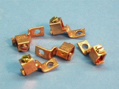
Rule of thumb is to a separate ground lug for each cable to be grounded - never double up cables anywhere...
I of course also ran 4AWG size cables both 12VDC HOT and GROUND to the HD rotary BLUE SEA switches in the battery area.
Bonding to me is a term used around the additional power sources of Generators and Inverters tieing the NEUTRAL and GROUND pins together to satisfy the GFCI tripping problems...
Roy Ken