myredracer
Mar 01, 2015Explorer II
Q on install of Reese cam arm bracket
I didn't get around to installing the cam arms on our TT which was new last year and ran without it and now I want them in for this season. I had these installed on a previous TT with just under 1K lbs tongue weight and the Reese forming screws didn't stay tight and the threads got damaged. This time I want to do something better. The WDH was purchased in 2013.
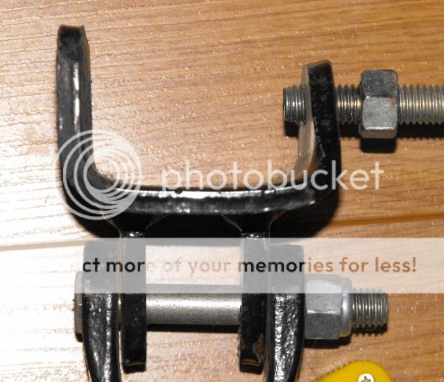
Our brackets in the photo have a radius between the bottom horizontal part and the side of maybe about 1/4" radius. The bottom of the bracket has a pronounced dip in of about 1/8" from the side to the center.
I've read on this forum about some installing a 1/4" plate on the outer side of the A-frame and grinding a radius on the bottom to match the radius on the bracket. My plan is to install nuts on the inside of the A-frame tubing by tack welding 2 nuts to a small plate and pushing it in place with a 6' long threaded rod that I can remove afterwards. I'm also thinking of plug welding the plate inside the A-frame to the A-frame so that the flange bolts could be removed without the inside plate moving.
Is most of the force taken up between the A-frame and bracket on the outer side of the A-frame or is it intended for the bottom of the A-frame to rest in the bottom of the bracket? Is installing a 1/4" plate between the A-frame and bracket actually going to help anything much? With such a curve on the bottom of the bracket, there isn't much surface area to rest against the bottom of the A-frame, plus it may not square to the outer part of the bracket.
I'm so sure I like the arrangement/placement of the square head setscrew on the inside of the A-frame with just the outer side of the A-frame in contact with the bracket as it could allow vertical movement (I think). Would it make sense to mount a nut inside the A-frame and another flange head bolt and then use spacers of some sort to take up space between the bracket and A-frame (approx. 1/2"?)?
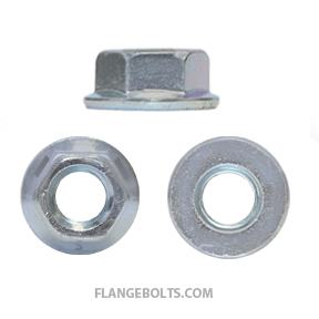
I will use a 1/2-13 flange head bolt and flange head nut so I get more contact area between the parts that may help to keep things tight. I'm also going to use Loctite red or blue as well. Bolt and nut will be as in pics.

Our brackets in the photo have a radius between the bottom horizontal part and the side of maybe about 1/4" radius. The bottom of the bracket has a pronounced dip in of about 1/8" from the side to the center.
I've read on this forum about some installing a 1/4" plate on the outer side of the A-frame and grinding a radius on the bottom to match the radius on the bracket. My plan is to install nuts on the inside of the A-frame tubing by tack welding 2 nuts to a small plate and pushing it in place with a 6' long threaded rod that I can remove afterwards. I'm also thinking of plug welding the plate inside the A-frame to the A-frame so that the flange bolts could be removed without the inside plate moving.
Is most of the force taken up between the A-frame and bracket on the outer side of the A-frame or is it intended for the bottom of the A-frame to rest in the bottom of the bracket? Is installing a 1/4" plate between the A-frame and bracket actually going to help anything much? With such a curve on the bottom of the bracket, there isn't much surface area to rest against the bottom of the A-frame, plus it may not square to the outer part of the bracket.
I'm so sure I like the arrangement/placement of the square head setscrew on the inside of the A-frame with just the outer side of the A-frame in contact with the bracket as it could allow vertical movement (I think). Would it make sense to mount a nut inside the A-frame and another flange head bolt and then use spacers of some sort to take up space between the bracket and A-frame (approx. 1/2"?)?
I will use a 1/2-13 flange head bolt and flange head nut so I get more contact area between the parts that may help to keep things tight. I'm also going to use Loctite red or blue as well. Bolt and nut will be as in pics.


