Forum Discussion

BFL13's avatar
BFL13
Explorer II
Jan 15, 2018

Alternator to House Battery Charging Test Results UPDATE

Update 18 Jan--

This is for my rig with its particular wiring (some changes to original done by me). Has the dreaded Ford 2G alternator.

Testing on a pair of 6s starting at about 55% SOC and 12.2v (so can accept lots of amps--more than from my alternator charging so not a bottleneck for the test) Used Trimetric for house battery voltage and amps, and multimeter for engine battery voltage.

Engine was idling for the test except as noted. Engine hood up, so a bit longer to warm up maybe. Started test at 0925

0925- Cranked engine--immediate 37 amps but tapering fast.
0927- 28 amps/13.3v Engine batt 14.59 volts
0930- 26a/13.3v --14.40v
0935- 24.4a/13.2v--14.35v
0940- 23.0a/13.2v--14.29v Revving made amps go down by about 1 amp
0945- 21.9a/13.2v--14.26v Closed hood to see if more heat matters
0950- 19.1a/13.2v--14.18v engine is warmed up to "normal" Stopped.

Restored 10.7 AH on Trimetric in the 25 minute test.
70 Replies

  • ktmrfs wrote:
    is there a way to enable a high idle on the MH? something on the order of 1200 rpm or so. If so, you may be able to get more out of the alternator, higher voltage and more current. Alternators are rated for max output at a fairly high rpm, well above engine idle.

    1200 rpm should sufficient for close to maximum output.

    Buy a clamp style meter like this one Clamp it on the output wire of the alternator, then turn on all the lights, wipers, etc. and see what it reads. Check the voltage at engine battery. Check the voltage at the house battery. I guarantee you the voltage at the house battery is NOT higher than the engine battery and that is probably INADEQUATE to fully recharge the hose battery, even after hours of driving.
  • Mex, what accounts for the initial 37 amps I saw and the quick taper to 28?

    Starting (chassis) battery voltage only got measured at 14.59v after the quick decline. Was starting battery voltage higher at first and I missed that? If so, I can set up a test on that but I will need an assistant ( such as DW in the driver's seat with me at the battery)


  • And how does one "push" more current through a ...


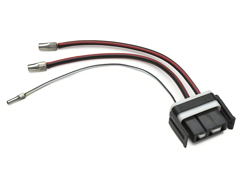
    After hair-raising proof with amperage and thermal scans, even with soldered 10 gauge wires and noodging the connector so tight joining male to female, I imposed a STRICT limit of 30-amps with "push-on" terminals.

    Bosch got smart and replaced the .250" push on blades on it's 70-amp relay to .375".

    Even so, even with Delco Packard 56 female terminations, my limit for .375" push-on's is 40 amps. My thermocouple makes for an inarguable tattle-tale.

    Ford did NOT have a "Better Idea" when it came up with this wonder.

    10,000 harness fires corroborate my opinion.
  • ktmrfs wrote:
    is there a way to enable a high idle on the MH? something on the order of 1200 rpm or so. If so, you may be able to get more out of the alternator, higher voltage and more current. Alternators are rated for max output at a fairly high rpm, well above engine idle.

    Still not an ideal way to charge batteries, but does make a difference.


    All I got from a higher idle was fewer amps to the house battery. I think the engine stuff then needed more of what the alternator supplied, so the house sucks hind tit.

    I do see that alternators including the Ford 3G ones, have a higher amps rating for when revved up.

    "find 3Gs in pick-your-parts boneyards that put out 90-100 amps at idle and up to 160 amps at highway operating speed."

    My 2G is apparently rated around 60-75 amps, so that 37 amps I got at first seems decent? No idea really as to what is "normal" with these things.
  • is there a way to enable a high idle on the MH? something on the order of 1200 rpm or so. If so, you may be able to get more out of the alternator, higher voltage and more current. Alternators are rated for max output at a fairly high rpm, well above engine idle.

    Still not an ideal way to charge batteries, but does make a difference.
  • Gjac wrote:
    Thanks for posting. I have a similar issue with my setup. When my 2 6 V GC batteries are at 50% SOC I am only seeing 8.7 amps at the batteries from my 180 amp alternator. Wiring is original from the OEM alternator, which I think was 85 or 110 amps. I have a cheap Chinese volt/ammeter that I don't know how accurate it is but I expected to see more amps going into the batteries also.


    That seems low amps even so. Mine has original #10 wire for miles of pos path and the frame for the neg path. Still got around 20 amps on a low battery. Perhaps there is a loose connection or two adding to your path resistance.

    You can do a couple of easy things where you can see it all by the engine. Where it goes alternator/starter relay/battery post/isolator/CB/wire back to house, you can :

    A. Move the wire from battery post to isolator and make it fatter and now run from starter relay to isolator.
    B. Cut the wire from CB to where it goes out of sight through the firewall if it is long enough to make this worthwhile and replace it with fatter wire.

    In fact on mine I made that fatter wire go from the isolator to near the firewall and used the CB as a connector between the fatter wire and the original wire (to which I added a ring terminal where I had cut the wire)

    Back at the house battery area, find the pos wire coming from up front and fatten the part that you can get at from there to the battery (should be another CB at that end of the wire so there is a "fuse" at each end protecting the wire where it is out of sight between the front and the house batts)

    That is about all you can do with the pos path without getting complicated, routing a fatter wire all the way.

    C. Check the neg path frame connections for corrosion if you can find them. That might even be the real problem with the low amps on yours.

    If you have long jumper cables, you can by- pass the pos and neg paths individually to see if amps jump higher with one or the other path by-passed. If so, then you know where to look.
  • I am getting tired of REPEATING this this. It has been covered in at least a dozen different posts in the past 3 or 4 months. Here it is AGAIN !

    Vehicle alternators/charging systems are NOT a good way to charge a "house" battery bank. You just proved that ! Heavier gauge wiring will help a little but not a lot. With out going into the specific details, if you want to PROPERLY charge a deep cycle battery bank you need to do the following:

    • Install a DC-DC boost converter between the vehicle battery and the house battery. Its output should be set to about 16V. (These are cheap on eBay of Amazon. No housing or wiring;
      Don't believe the maximum amps. It you "push" it hard, you need a housing with a fan.)
    • After the boost converter, install a deep cycle solar charge controller (An inexpensive PWM model is fine.)
    • Connect the output of the solar charge controller to the battery bank
  • Gjac's avatar
    Gjac
    Explorer III
    Thanks for posting. I have a similar issue with my setup. When my 2 6 V GC batteries are at 50% SOC I am only seeing 8.7 amps at the batteries from my 180 amp alternator. Wiring is original from the OEM alternator, which I think was 85 or 110 amps. I have a cheap Chinese volt/ammeter that I don't know how accurate it is but I expected to see more amps going into the batteries also.
  • Yes some fatter wiring would be better for the long ways between the front and middle of the MH. This test shows how it is now. Gives me a "baseline" for any improvements.

    I was surprised revving did not make the amps go up any. Actually went down a bit compared with idling. I thought alternator voltage would drop to 13.8ish fairly quickly, but nope.

    Huge PITA to improve that wiring any more than done already at the easy access parts, so have to decide if the extra amps would be worth it for any scenario that has alternator charging being important.

    Not at all clear that getting say 35 amps is any better than 25 amps for an hour of idling. 10AH is peanuts.

    Another thing with way higher amps is whether the battery bank would even be low enough to accept that many. Depends on the scenario, and how many times a year for each scenario when calculating "worth it".
  • BFL13 wrote:
    Has the dreaded Ford 2G alternator.
    I see a dread wiring issue more than any issue with the 2G.
    A full volt drop is terrible. Get that drop adjusted to .3 or less for best results.