subcamper
Jun 06, 2014Explorer II
Create-A-Breeze Motor Repair
This fix procedure is for the do-it-yourself guys that like to fix things and don't mind a little fiddling here and there.
I had the motor in our Rockwood Create-A-Breeze fan in the bathroom ceiling replaced for free by Fantastic Fan twice in its 9-year lifetime so far. At this point, there are no more free fans (and I can't really expect one at this point), so I decided to see what happened to the motor.
After removing the motor/fan from the vent assembly, I removed the fan from the motor (allen setscrew on fan) and then the motor from the plastic motor case (3 phillips-head screws).
This left me with a "pancake" style motor with two housing halves riveted together. Make sure to mark the position of the top and bottom housings for later reassembly. I used a 3/16" drill bit to drill out the 3 rivets. Then I pried the two housing halves apart (there appeared to be a small amount of adhesive used)and ended up with the following:
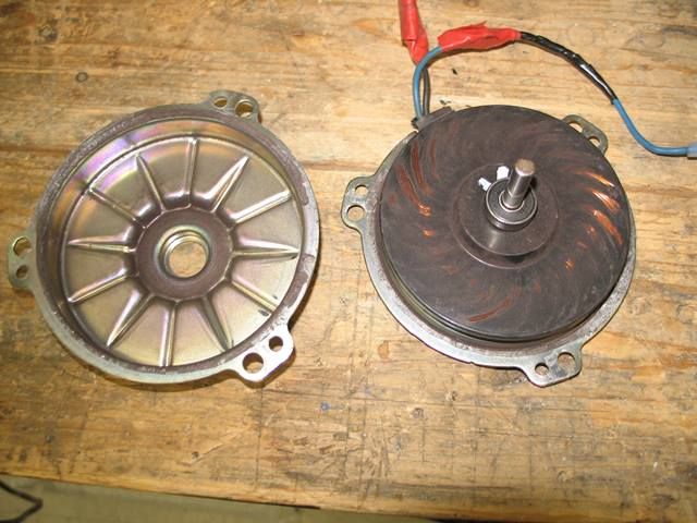
One the right is the rotor assembly still inserted into the lower housing shell. Grab the rotor by the bearing and pull straight up while spinning slightly (to help clear the brushes) until the rotor is free. Here is a picture of the rotor after removal:
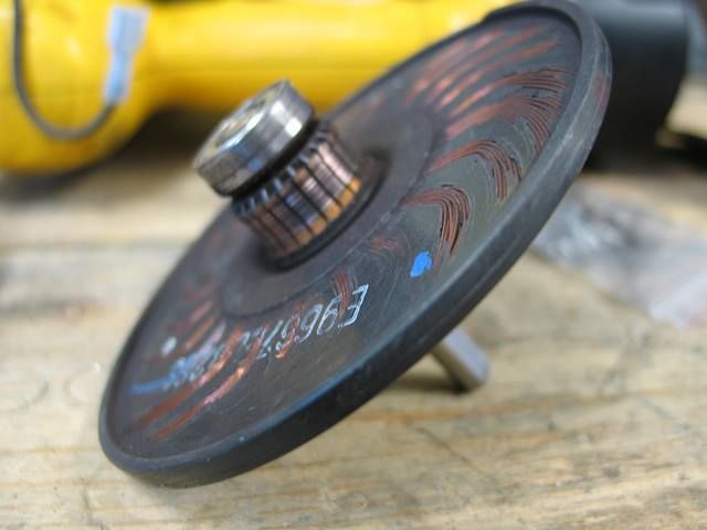
What you will see in the bottom housing is the following:
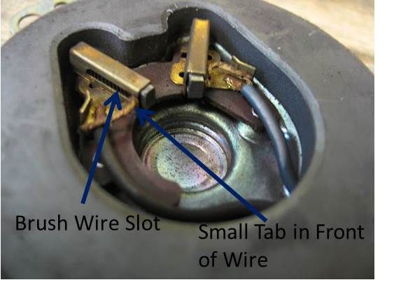
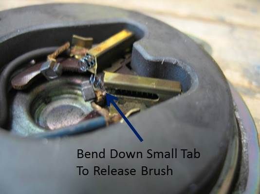
The large diameter magnets attached to the housing are very powerful and will try to attract any steel tools! Note that the brush wire is at the extreme front of the slot, indicating that the brushes are completely worn out and there is no travel left in the assembly to push the brushes against the commutator(on the rotor). I also noted the location of a small tab on the brush housing that keeps the brush from falling out completely. This tab needs to be bent outward and down so the wire (and attached brush)can be removed completely from the brush housing. After bending the tab and removing the brushes from the housings, you have the following:
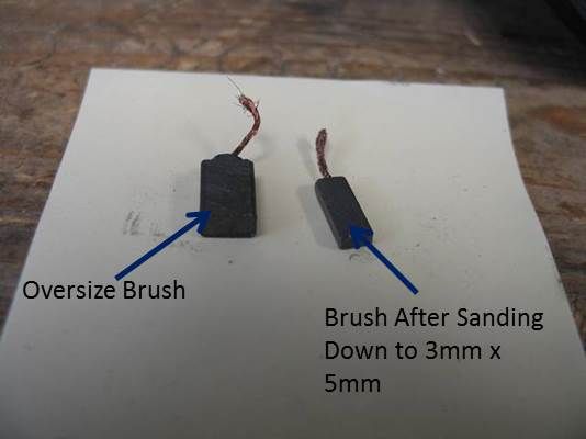
The dimensions of the brushes was about 3mm x 5mm (0.118" x 0.197"). The length looks to have been about 1/2" long (12mm) based on the length of the wire slot. A quick internet search showed that either there were no identical stock sizes or a custom place could make them but charged a lot. I happened to have a set of extra brushes I received with a Harbor Freight tool. The brushes were larger, but the carbon material is easy to sand down. The following picture shows the HF brush before and after sanding to size:
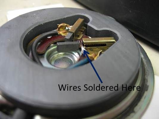
I cut the brush wire that was attached to the original brushes and also cut the wire attached to the new brushes so the total length of brush wire would be close to the original length. Here is a picture showing the new brushes installed and the wires soldered:
After the new brush is pushed into the housing(against the spring), the tab is bent back up to keep the brush from popping out completely.
The hardest part of the whole task is to reassemble the rotor to the bottom housing (containing the brushes). The new brushes stick out too much and you can't just push the rotor straight down. What I did was to make a tool from a piece of wire with a small bend at the end to pull each of the brush wires back to retract the brushes. I had to keep pulling on the wires with the tool while inserting the rotor downward into the housing fully. Just before the rotor was down all the way, I pulled the wire tool out and pushe dthe rotor down the final small amount. I forgot to take a picture of this process, sorry. Since the two brushes are at a 90 degree angle to each other, you can com in slightly sideways with the rotor to help push the brushes in. Its really a "feel" thing that's hard to describe in words. Spin the rotor by hand to make sure there is a smooth feel.
Next step was to put the top cover back on. If it snaps down rotated out of position, it's difficult to rotate by hand so try to align the mounting tabs as close as possible while snapping the housing down. If you need to rotate the top housing (like I did), you can use a pair of channelock pliers between the upper housing tab and the lower housing tab until they are perfectly aligned.
The final step was to put 3 new 3/16" diameter pop rivets to hold the two housing halves together.
I tested the motor by hooking it up to 12VDC to make sure it worked smoothly.
After reassembling into the vent assembly, it seems to work perfectly.
Hope this helps somebody.
Steve
I had the motor in our Rockwood Create-A-Breeze fan in the bathroom ceiling replaced for free by Fantastic Fan twice in its 9-year lifetime so far. At this point, there are no more free fans (and I can't really expect one at this point), so I decided to see what happened to the motor.
After removing the motor/fan from the vent assembly, I removed the fan from the motor (allen setscrew on fan) and then the motor from the plastic motor case (3 phillips-head screws).
This left me with a "pancake" style motor with two housing halves riveted together. Make sure to mark the position of the top and bottom housings for later reassembly. I used a 3/16" drill bit to drill out the 3 rivets. Then I pried the two housing halves apart (there appeared to be a small amount of adhesive used)and ended up with the following:
One the right is the rotor assembly still inserted into the lower housing shell. Grab the rotor by the bearing and pull straight up while spinning slightly (to help clear the brushes) until the rotor is free. Here is a picture of the rotor after removal:
What you will see in the bottom housing is the following:
The large diameter magnets attached to the housing are very powerful and will try to attract any steel tools! Note that the brush wire is at the extreme front of the slot, indicating that the brushes are completely worn out and there is no travel left in the assembly to push the brushes against the commutator(on the rotor). I also noted the location of a small tab on the brush housing that keeps the brush from falling out completely. This tab needs to be bent outward and down so the wire (and attached brush)can be removed completely from the brush housing. After bending the tab and removing the brushes from the housings, you have the following:
The dimensions of the brushes was about 3mm x 5mm (0.118" x 0.197"). The length looks to have been about 1/2" long (12mm) based on the length of the wire slot. A quick internet search showed that either there were no identical stock sizes or a custom place could make them but charged a lot. I happened to have a set of extra brushes I received with a Harbor Freight tool. The brushes were larger, but the carbon material is easy to sand down. The following picture shows the HF brush before and after sanding to size:
I cut the brush wire that was attached to the original brushes and also cut the wire attached to the new brushes so the total length of brush wire would be close to the original length. Here is a picture showing the new brushes installed and the wires soldered:
After the new brush is pushed into the housing(against the spring), the tab is bent back up to keep the brush from popping out completely.
The hardest part of the whole task is to reassemble the rotor to the bottom housing (containing the brushes). The new brushes stick out too much and you can't just push the rotor straight down. What I did was to make a tool from a piece of wire with a small bend at the end to pull each of the brush wires back to retract the brushes. I had to keep pulling on the wires with the tool while inserting the rotor downward into the housing fully. Just before the rotor was down all the way, I pulled the wire tool out and pushe dthe rotor down the final small amount. I forgot to take a picture of this process, sorry. Since the two brushes are at a 90 degree angle to each other, you can com in slightly sideways with the rotor to help push the brushes in. Its really a "feel" thing that's hard to describe in words. Spin the rotor by hand to make sure there is a smooth feel.
Next step was to put the top cover back on. If it snaps down rotated out of position, it's difficult to rotate by hand so try to align the mounting tabs as close as possible while snapping the housing down. If you need to rotate the top housing (like I did), you can use a pair of channelock pliers between the upper housing tab and the lower housing tab until they are perfectly aligned.
The final step was to put 3 new 3/16" diameter pop rivets to hold the two housing halves together.
I tested the motor by hooking it up to 12VDC to make sure it worked smoothly.
After reassembling into the vent assembly, it seems to work perfectly.
Hope this helps somebody.
Steve