Forum Discussion

DiskDoctr's avatar
DiskDoctr
Explorer
Jul 01, 2017

Help me choose a fuse and shunt

Four 6v golf cart batteries connected together with 2AWG wire, then 4/0 wire used to connect to the inverter posts. Inverter posts also connect to PD9270 converter/charger.

According to wiring guides and help from folks here, it should be good to 400amps DC.

The inverter is the biggest load, a Xantrex ProSine 1800 that surges to 2800amps max (momentary).

I'd like a fuse setup that isn't too bulky, is easy to check, protected from shorts against the battery box lid (and rugged housing), and looks nice.

I would also like to add a shunt to keep an eye on everything battery related. It's been recommended I use a 200 amp shunt between battery negative terminal and negative lead (right?)

Currently the frame ground is too small and the original wiring uses breakers (reverse wiring protection or overload?) that are corroded and must be replaced.

I'm thinking a monster-sized frame ground lug/bar with a 2 AWG wire from the inverter's negative terminal to the new frame lug, where it joins the existing line to all the house DC via distribution panel, brakes, etc.

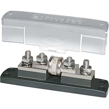
Here are some styles I'm looking into.


shunt


I like the clear housings that take wire into each end and crimp it, but nothing I've found supports the 4/0 cable, so I'm looking at terminal threaded posts/bolts.

Ideas? Pics? Experiences?

Thanks!

20 Replies

  • BFL13 wrote:
    ...If you get the Trimetric, you will need its 500a shunt, not the little 100a one. (IMO just bite the bullet and get the Tri instead of fooling around with cheaper kinds that can't do it all)


    $200 :(

    Eventually may build out Arduino, but looking for something to get started. If we can find a decent hall effect ring in this amperage, I'd be happier to use it. If we go over the amps on it, there shouldn't be any damage to the sensor, right?

    The inverter really wants direct cables to the batteries, according to all the installation docs I read. Make sense ?

    Same with the converter/charger, then branch to the frame lug and feed to the camper/distribution box.

    It may not be "ideal" but should be fine, right?
  • pianotuna wrote:
    Hi,

    I prefer to use Hall effect ammeters--no shunt needed.


    Got a link to one at least 200 amps?
  • SIDE NOTE
    Go online, perhaps to eBay or Amazon.

    Find a good looking 12-volt rated LED pilot lamp, and configure a way to have a stylish bracket for it. My personal choice is a blinking 5mm green chrome bezel LED.

    If the inverter fuse should ever fail, the blinking light screams at me "FAILURE!" So I do not need a flashlight to check fuse integrity at night.

    Wiring the LED is child's play. There will be two long wires extending from the LED. One red the other, black.

    Connect the RED wire to the BATTERY side of the fuse
    Connect the BLACK wire to the INVERTER side of the fuse.

    Quicksilver has Klixxon toggle breakers. Every 12 volt breaker has a 5mm red LED wired across it and every 120vac breaker has a 5mm blue LED wired across it.

    I open the panel and don't even have to "look".

    The main breaker has an LED has well.

    A product of being incredibly lazy.
  • j-d's avatar
    j-d
    Explorer II
    That Blue Sea fuse looks SOLID and I like the idea of the Fuse being bolt-on without disturbing the bolt-on terminal connections. Never heard a bad thing about a Blue Sea product (except the price) and I read a lot about them on a boating forum as well as here.
    Cheaper on Amazon, as are the spare "T" fuses. The way some are priced, could be wise to buy a second assembly, use the fuse if needed, and have a spare "body" for a future project.
  • I would install a second #2 jumper between the batteries.
    I agree on a larger capacity shunt.
  • The existing neg wire to the frame from the neg battery post will now go from the shunt's outer end to the frame. It can be the same gauge as now since it will not carry any more amps than before.

    It will not go from the inverter neg. (especially if the inverter is also chassis grounded to the frame--things can get weird in the inverter's GFCI receptacles)

    The inverter's neg wire will now go to the outer end of the shunt and not to the battery neg. Same with all the other negs like the solar controller's.

    You will now have a fat wire from the inner end of the shunt to the neg battery post that needs enough ampacity to carry the total of all the amps arriving (or leaving depending on your country :) ) at the outer end of the shunt at any one time. (Inverter running MW plus water pump plus lights, and then the furnace comes on too, eg.)

    Your fuse(s) go on the pos wires and have nothing to do with the shunt etc on the neg wires. Fuse size for the wire gauge(s) One big fuse does not cover all sins. Each branch wire to the buss needs its own smaller size fuse and then the fatter wire from the buss needs a big fuse.

    Your shunt size should go with whatever monitor you are getting. If you get the Trimetric, you will need its 500a shunt, not the little 100a one. (IMO just bite the bullet and get the Tri instead of fooling around with cheaper kinds that can't do it all)
  • Colo Native wrote:
    this is the one I use
    http://www.imarineusa.com/bluesea5502classtfuseblock225-400amp.aspx


    That's a nice one, but also about $70 or so for the mount and fuse. Might not have a choice but to spend like that, it's pretty beefy...

    What about a shunt for monitoring amps?
  • this is the one I use
    http://www.imarineusa.com/bluesea5502classtfuseblock225-400amp.aspx