Ok so I got A samlex 600 watt inverter, and remote switch, and ATS.
I have 3 more questions I need to figure out.
The wire run will be somewhere around 12 to 14 feet to reach the installation area (so I can install next to the main panel).
Manual says I need to run 1/0awg wire for a 10 foot run with an 80 amp fuse. That's huge!
According to other charts it looks like 4ga wire would be plenty. The inverter itself looks like it will only take in 4awg wire so if I ave to run 0ga I'll need a distribution block to step down the wire size to 4awg before going into the inverter.
Can I get away with just running 4awg fine stranded car audio wire?Finally to make it easier to bypass the 120v->12v converter I have decided to instead run power from the main breaker to the ATS, and run the output from the ATS into the lower breaker (it has 15 15 amp breakers on it they provide power to all the trailer outlets).
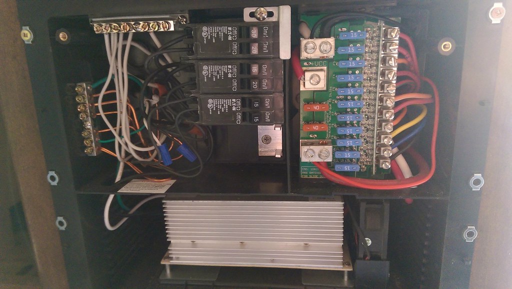
My problem is I don't know if it is possible to run the output line of the ATS into the existing breaker, it looks like these breakers pop onto the main buss?
Is there a way I ca run a wire to the input side of he 15/15 breaker but leave it mounted where it is?Finally, Do I really need to ground the inverter to the frame? It has +, -, and ground inputs and suggests grounding it to the vehicle frame
I have attached some pictures.
 trailer_inverter_wiring_revised
 by
glamisduner, on Flickr
This is the new wiring diagram, does not need any relays, and isolates the converter as well as will not allow high output devices to appear to be on and ready to use.
 2015-12-09_11-43-58
 by
glamisduner, on Flickr
The dual bottom breaker is the one I need to isolate from the main buss now. Is there a way I can cut off the post it is plugged into and instead feed a wire to it? Maybe I can cut the buss and bolt the ATS wire into the lower 1/2 of it?
 2015-12-09_11-44-37
 by
glamisduner, on Flickr
Finally an approximate location of where I plan to install the inverter and ATS.
 2015-12-09_12-03-14
 by
glamisduner, on Flickr
Thanks in advance!