Forum Discussion
Andonso
May 17, 2018Explorer
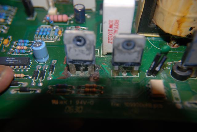
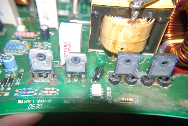
I removed the heat sink and it appears the mosfet on the far left is sort of crusty, appears from some sort of corrosion? and part of the PCB paint has flaked off, the mosfet next it doesn't appear to be as bad.
The mosfet markings have been smeared with some sort of pen so I'm not able to find a part number.
the documentation does have some specifications and also much detail on how the mosfets work with other parts of the converter.
Q2a & Q2b - 24 A, 500 V, 20 on resistance
I did find a diode mode for my dmms. with the ->| symbol. I attempted some testing moving the dmm probes around. The bottom of the mosfets have plastic tubing. When I tested them from the opposite side of the board I got mixed results. Holding the pos+ and neg- probes on the source and and drain there is momentary low voltage with sometimes a beeping then the meter goes to zero, while the mosfet on the right maintains a low reading such as .8xx .9xx. Sometimes the mosfet on the left reads only zero when probing the two outer left and right pins.
I don't know for certain if the gate is in the middle, drain on the left and source on the right? viewing the mosfet as from the pics from the back side. As don't have a part number for the mosfets.
Tomorrow I'll get some electronics cleaner and clean them up. I may need to remove the plastic tubing near where their soldered to the pcb.


Q2b is on the left and Q2a on the right.
Pics
The mosfet markings have been smeared with some sort of pen so I'm not able to find a part number.
the documentation does have some specifications and also much detail on how the mosfets work with other parts of the converter.
Q2a & Q2b - 24 A, 500 V, 20 on resistance
I did find a diode mode for my dmms. with the ->| symbol. I attempted some testing moving the dmm probes around. The bottom of the mosfets have plastic tubing. When I tested them from the opposite side of the board I got mixed results. Holding the pos+ and neg- probes on the source and and drain there is momentary low voltage with sometimes a beeping then the meter goes to zero, while the mosfet on the right maintains a low reading such as .8xx .9xx. Sometimes the mosfet on the left reads only zero when probing the two outer left and right pins.
I don't know for certain if the gate is in the middle, drain on the left and source on the right? viewing the mosfet as from the pics from the back side. As don't have a part number for the mosfets.
Tomorrow I'll get some electronics cleaner and clean them up. I may need to remove the plastic tubing near where their soldered to the pcb.
Q2b is on the left and Q2a on the right.
Pics
About Technical Issues
Having RV issues? Connect with others who have been in your shoes.24,396 PostsLatest Activity: Jun 24, 2026