Forum Discussion

dmullen's avatar
dmullen
Explorer
Dec 08, 2014

PI EMS-HW30C Installation Question

I was about to install a Furrion Conversion Kit to eliminate my mouse hole and thought this would be a good time to also install a Progressive Industries EMS-HW30C surge protector. I have about 8 inches of slack coming out of the mouse hole where I cut off the power cable. I will wire the cut end of the power cable into the back of the conversion kit outlet which replaces the mouse hole door so that I can now have a detachable power cable. I would then cut the power cable again and wire it to the input of the EMS-HW30C and then wire the other end of the power cable to the output of the EMS-HW30C. Would this be a proper and sound install?
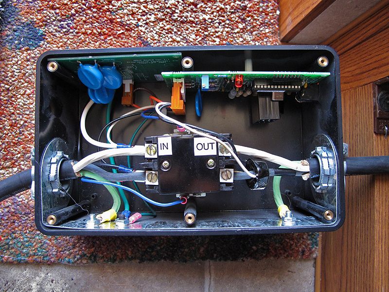
  • IMO, the grounding as shown in the picture above is adequate. Those screws are attached to a wide piece of galvanized metal which also includes the cable mounting clamps. I'd go with it. YMMV
  • The EMS will be delivered tomorrow so I will probably tackle this project this weekend. Anyone else have an opinion about the conversation so far before I do the install? I want to make sure I'm doing everything right. I'm still not sure if I am understanding the installation of the grounding wires correctly.
  • myredracer wrote:
    The EMS comes with a little baggie with screws and some ring terminals (IIRC it's more than one) to use on the small green grounding screw on the side of the interior of the EMS. Take one of the ring terminals and crimp it onto a piece of green or bare wire. If you don't have one, you'll need to buy a crimper/stripper but they are cheap. This connection inside the EMS is for bonding and sensing and can be a smaller gauge like #14 .

    It's very important to maintain the integrity of the ground wire inside the shore power cable (from the panel all the way to the shore power plug) by not having substandard splices/connections and by not reducing the wire gauge anywhere. I'm just going by memory, but I seem to recall from our EMS that the grounding screw inside the EMS is rather small, as is the ring terminal. I also seem to recall that the instructions being vague or silent on exactly how to connect the ground wires.


    Looking at the picture above do you still think the grounding screws are not adequate enough?
  • The EMS comes with a little baggie with screws and some ring terminals (IIRC it's more than one) to use on the small green grounding screw on the side of the interior of the EMS. Take one of the ring terminals and crimp it onto a piece of green or bare wire. If you don't have one, you'll need to buy a crimper/stripper but they are cheap. This connection inside the EMS is for bonding and sensing and can be a smaller gauge like #14 .

    It's very important to maintain the integrity of the ground wire inside the shore power cable (from the panel all the way to the shore power plug) by not having substandard splices/connections and by not reducing the wire gauge anywhere. I'm just going by memory, but I seem to recall from our EMS that the grounding screw inside the EMS is rather small, as is the ring terminal. I also seem to recall that the instructions being vague or silent on exactly how to connect the ground wires.
  • The EMS enclosure has a separate green grounding terminal for both the input and the output. Should I still wire the ground from both ends together and add a separate wire to just one of these grounding screws?

    Here is somebody's install that will be close to mine...
  • That is fine. Another thing I would do is check the existing hot, neutral and ground connections of the cable inside the converter panel and make sure they're snug. While in there, might as well take your screwdriver and check all the other terminations too.
  • Thanks for the information. All of the wiring to the EMS, both input and output, would be the stranded wire from the shore power cable. I have seen a lot of installs where the shore power cable is wired to the EMS on one end and then I see a romex cable on the other end. Mine is not like that. I will be using the big black shore power cable for both ends.
  • dmullen wrote:
    I was about to install a Furrion Conversion Kit to eliminate my mouse hole and thought this would be a good time to also install a Progressive Industries EMS-HW30C surge protector. I have about 8 inches of slack coming out of the mouse hole where I cut off the power cable. I will wire the cut end of the power cable into the back of the conversion kit outlet which replaces the mouse hole door so that I can now have a detachable power cable. I would then cut the power cable again and wire it to the input of the EMS-HW30C and then wire the other end of the power cable to the output of the EMS-HW30C. Would this be a proper and sound install?


    That is correct. Also, it's always good to leave some slack at each entry/exit to an enclosure in case something gets changed in the future or needs to be repaired.

    You likely have the stranded cable going directly to the converter panel now, but if it happens to be spliced to solid, connect to the terminals on the EMC with stranded wire (use piece of #10 shore power cable) rather than solid wire. There was a post earlier this year about someone who had overheating problems with the connections to terminals (with solid wire) and it may have been due to the way the terminal is designed. With a solid wire, you only get two positive connection points to the terminal as shown in the photo below. With stranded wire, there will be a greater surface area spread out between wire and terminal. You can do a splice inside the EMS. For the best splice if one or both are stranded, solder the wires together and use a wire nut like in the 2nd photo or use shrink tubing.

    If you already have stranded #10 all the way to the converter panel, you don't have to worry about the above as long as you maintain stranded wire in and out of the EMS.

    With the incoming and outgoing ground wires, connect them directly together, then with a separate ground wire to the grounding terminal in the enclosure.