cancel
Showing results for 
Search instead for 
Did you mean: 

Bent Main Frame Rail Below Slide - (Picture Heavy)

JBarca
Nomad II
Nomad II
Hello Fellow Campers,

I’m inquiring if you or someone you know has run into where the main frame rail (thin I beam style) bent down behind the rear spring hanger and if you know any of the details surrounding it? This is a somewhat technical & long post by it's nature and I will try to keep it short as I can and use pictures get the point across. I have searched the web for this type of failure and to date have not found this type of issue. I have found a lot of bent A Frames, spring hangers and I beam web cracks. Mine is different. I did find one where the frame did failed in a similar manner and it was here on RV.net. See here. Bent Frame and breaks However in this case, the camper was in an accident where the camper become air born, dropped down hard on the road and bent the frame rail in one very large event.

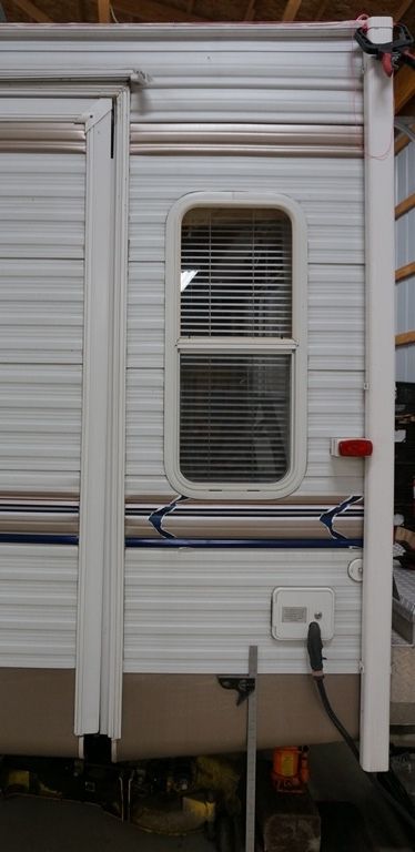
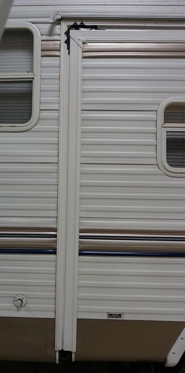
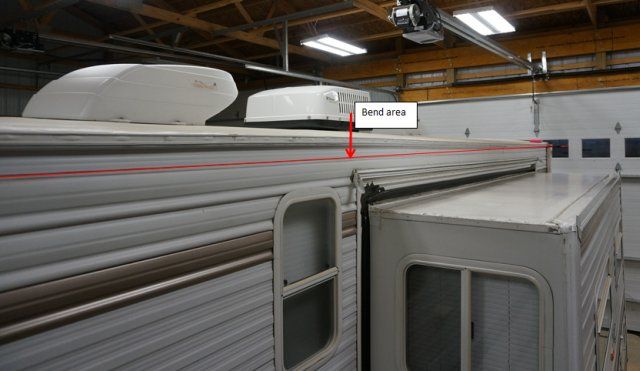
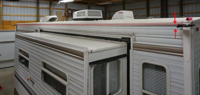
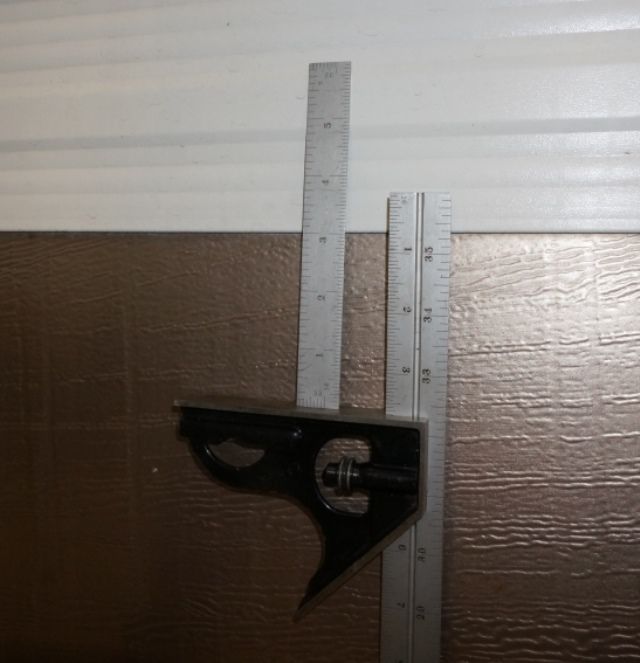
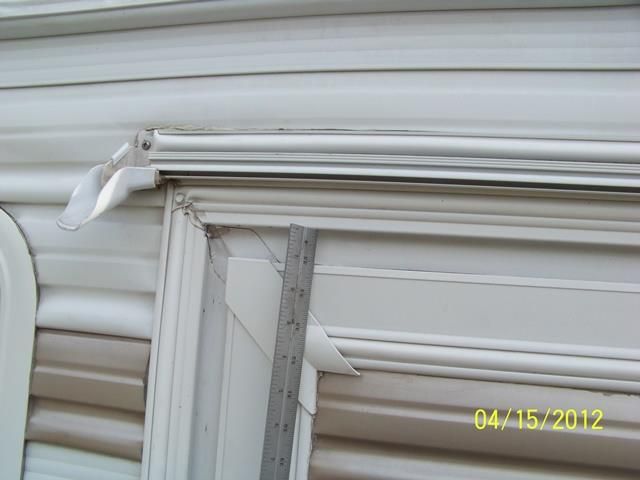
Background: This past fall on our last campout, our slide room would no longer retract without heavily binding on the top rear and lower front sides of the slide. This issue has been ongoing for several years and has progressed worse over time. Basically, the slide opening in the camper wall is out of square in relation to the square slide room. In the past I could fudge the slide adjustment to get the system to work. I am now out of the adjustment.

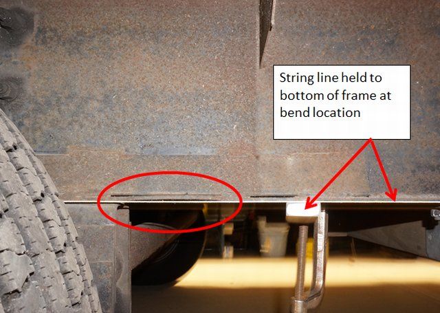
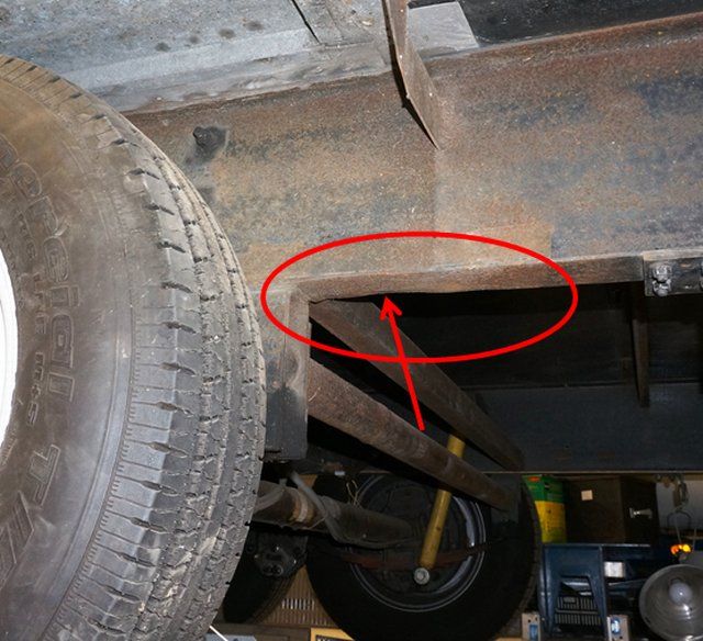
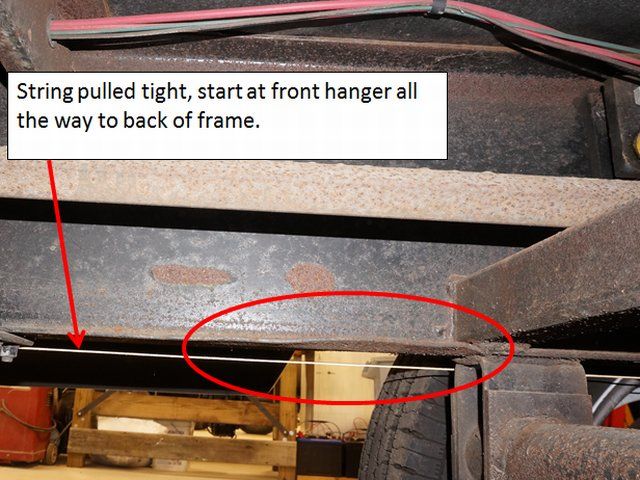
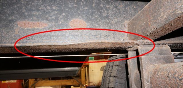
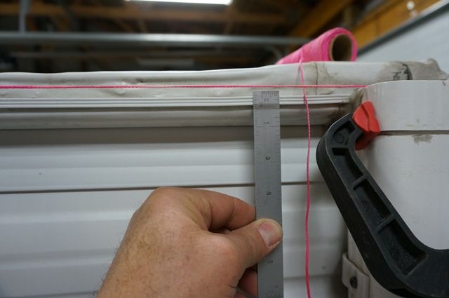
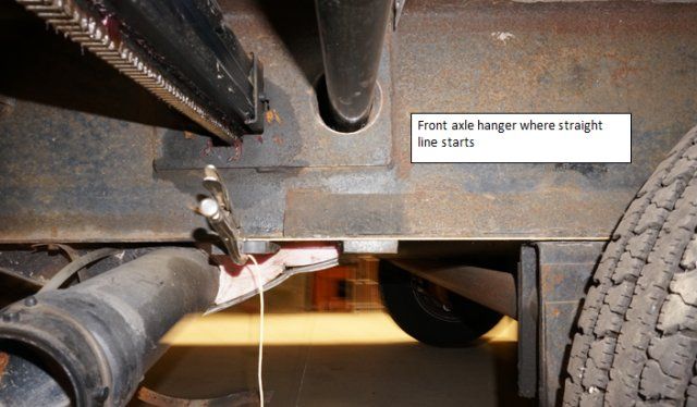
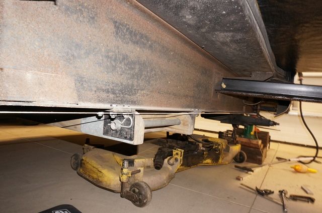
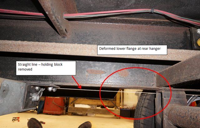
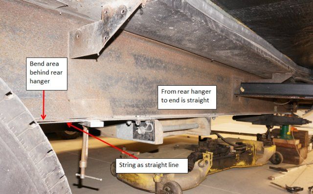
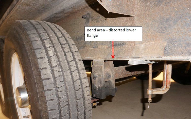
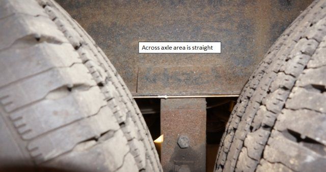
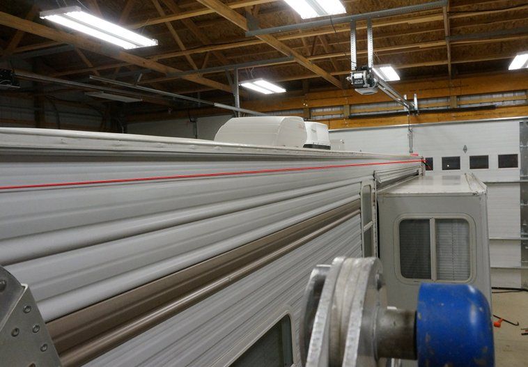
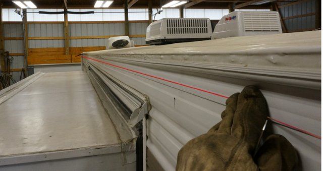
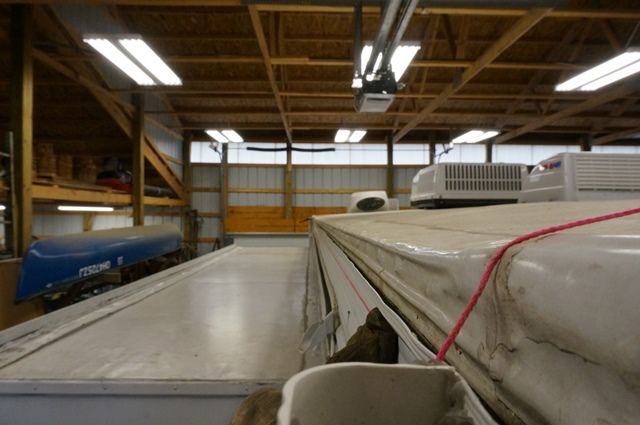
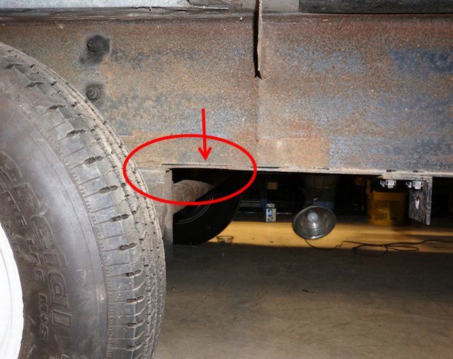
After measuring the camper, I found the main frame rail below the slide is bent down just aft of the rear axle spring hanger. By pulling a string along the bottom of the frame, starting at the front spring hanger all the way to the rear camper wall, the area between the spring hangers is straight. There is a bend down aft of the rear hanger and then the frame is straight all the way to the back wall. If I jack up the slide side frame rail at the end of the frame 3”, the bottom of the frame is now straight and the slide opening is back to true square.

We bought the camper in Oct, 2007 and I have pictures documenting several upgrades over the years to the running gear. Added new axles to correct axle alignment, added; shocks, rubber equalizer, hanger stiffeners, self-adjusting brakes and 15 to 16” LT tire upgrade. Through these pictures I can see when the frame lower flange was straight and when deformation started.

During the summer of 2010, we were towing across NY state on I-88 heading west out of the Amsterdam area into Corning NY. The state had started resurfacing from the eastern end heading west, however the last 15 miles was still old road. That last 15 miles was old concrete road and brutal with pot holes. We were somewhat trapped having to stay with in the right lane with no exits until we got off. Passing semis/cars etc. in the left lane and It was pot hole after pot hole. I slowed to 45 to 50mph and dodged the pot holes I could and not create a speed hazard on the road. When we made it to camp, the inside of the camper was the worst shaken up ride we have ever had. At this time, I had no idea the frame may have been affected.

I have pictures months before our summer trip showing the frame was not yet deformed. By the end of 2010, the pictures were showing that lower flange deformation had started just I did not realize what it meant. After the event, we did a large quantity of normal towing which went on for the next 6 years but none with a pot hole cluster like I-88. The slide opening problem started around 2010 and become worse over time. At this point in my investigation, I feel the I-88 towing event started the lower flange deformation on the slide side frame rail and slowly over time continued to increase the frame rail bend downward making the slide opening out of square issue worse.

If you have seen this type of frame deformation before and have any details to it, please pass along. This is also a learning post that if you have the thin I beam type of frame, if you ever see any flange deformation, even slight damage, that is the sign of a problem. If I knew then what I know now, I could of corrected the issue much simpler back in 2010. I have a lot more information and can share if needed.

Here are pictures of the problem.

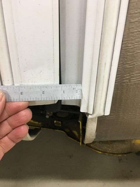
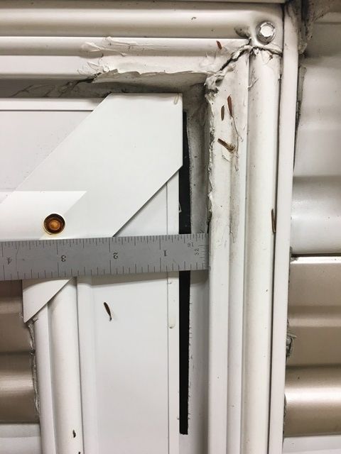
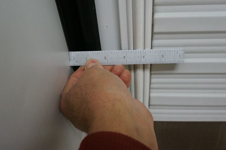
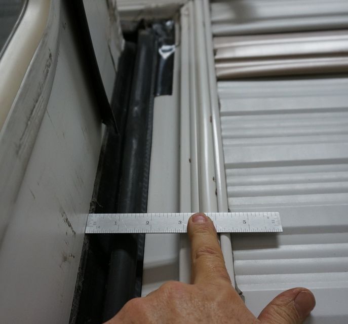
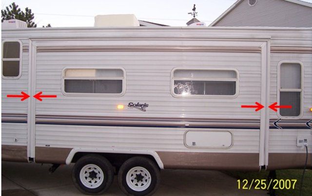
This first pictures are “before” the problem. Notice the gap between the slide flange and the camper flange. It is parallel like it should be. These pics are from the year we bought the camper.


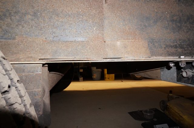
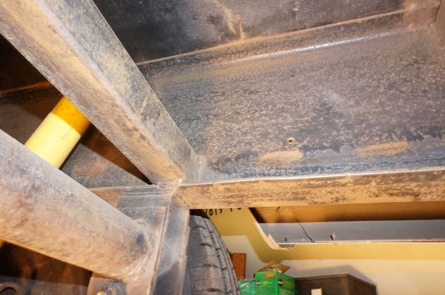
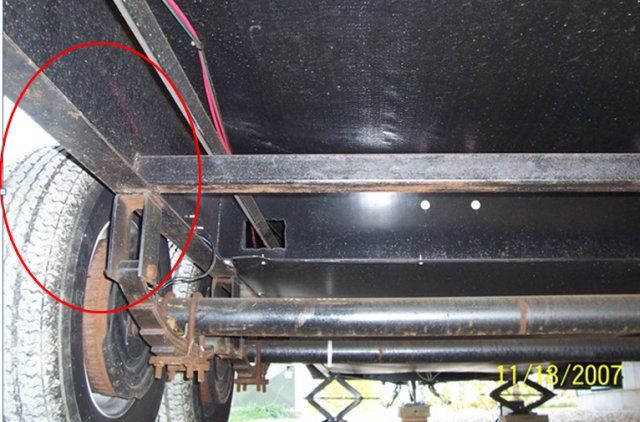
This is the lower flange behind the rear left frame hanger. Notice there is no distortion of the lower flange.

Now a few pics of time line leading up to current day. No damage yet in these pics.
2-8-2009 no damage
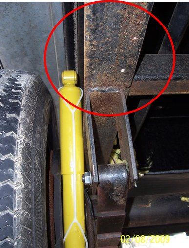

5-10-2009 adding reinforcement to prevent hanger flexing and lower flange bending and web cracking. No frame damage
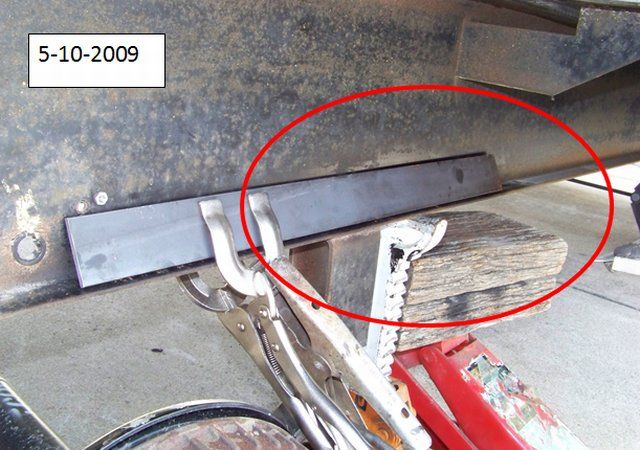
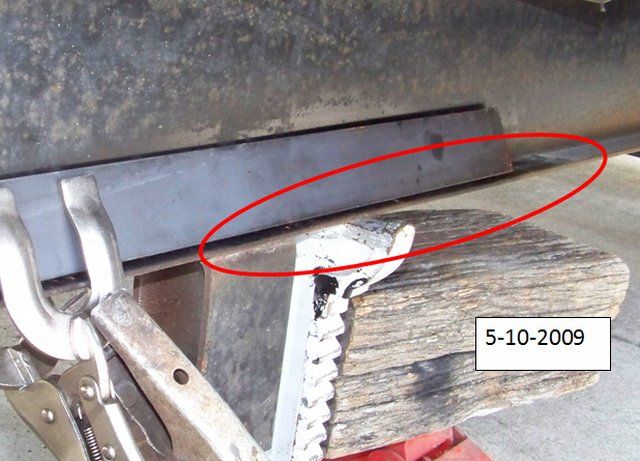


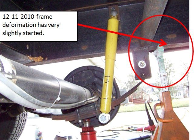
Now the start of damage. Picture taken on 12-11-2010 when adding rear shocks

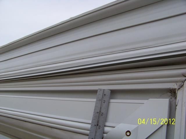
4-15-2012. Top rear of slide. Gap 3/4"

4-15-2012. Top front of slide. Gap 1 1/8" Must adjust slide arms to shift slide to fit camper hole better. This creates a situation inside were we do not lift off the carpet as much

More on the next reply.
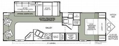
2005 Ford F350 Super Duty, 4x4; 6.8L V10 with 4.10 RA, 21,000 GCWR, 11,000 GVWR, upgraded 2 1/2" Towbeast Receiver. Hitched with a 1,700# Reese HP WD, HP Dual Cam to a 2004 Sunline Solaris T310R travel trailer.
33 REPLIES 33

JBarca
Nomad II
Nomad II
BoonHauler wrote:
I just ran across your thread, nice shop setup!!


Thanks, it has been a long time coming. The old one was much smaller and the longer camper was several feet too long to be inside...
2005 Ford F350 Super Duty, 4x4; 6.8L V10 with 4.10 RA, 21,000 GCWR, 11,000 GVWR, upgraded 2 1/2" Towbeast Receiver. Hitched with a 1,700# Reese HP WD, HP Dual Cam to a 2004 Sunline Solaris T310R travel trailer.

JBarca
Nomad II
Nomad II
Kayteg1 wrote:


Snip..
I am a welder when I need it and as I mentioned- probably the best fix is add welded plate on the side of I-beam.
Question is how to get the beam straight, or preferable bend other way for the time of the welding?

Will the center of the beam sag, when you jack up the ends?

In the past I was using 2x8 C-channels as ramps for equipment loading.
But one of those 10,000lb backhoes bend the chanel.
My reinforcement was adding welded rebar on the tips of C. But I did not have 10k press to straight it before reinforcement.
What I did was weld one end of the bar to the channel, than with torch warm up the bar in the range of 600F and then quickly weld the other end of the bar to the chanel.
Than I did 3" welds every foot.
Rebar when cooling down, shrank and pulled the chanel straight.
Obviously having trailer on the top of the chanel makes using torch a danger job, but similar effects can be done with cooling.


Hi Kayteg1,

I have the plan of a combo fix, partly bolt on, partly weld on that I feel good about and will work and fits my shop. Here is the quick word version, I sense you can follow it.

Yes, as you said, it will use 2 sister plates, one inside, one outside. To straighten the beam, support the frame from spreading, then at the bend area, stop drill a hole approx 1" down from the top flange. Saw the beam up from the bottom to the hole and jack the back of the camper up until the frame is straight and maybe a slight bit more for camber. Put the inside plate on, bolted in place on one side of the cut only at this point. Using E7018AC rod with this high strength steel, weld up the saw cut with the inside plate as a backing plate for a full penn weld. Grind and polish out the weld and bolt on the outside plate with the I beam sandwiched in the middle. Finish bolting the plates both sides of the saw cut frame together. The bottom flange needs gussets to stiffen up the lower flange and a bottom flange reinforcement that will weld on. I need to add the bottom flange reinforcements to the door side too to balance out the frame strength.

I want to see what Lippert can offer since Doug gave me a lead on them. I will post my method here in pic's/drawings shortly and the Lippert call may alter the plan, possibly even for them to do it if that makes good sense after I find out what they can offer.

To your question on, will the frame sag in the middle of jacking up the end? I know I can lift a good amount of the side of the camper when I lifted the end 3" to bring the bottom of the frame straight. 2,300# is on the force jack to get the 3". This 10" x 9 lb/ft beam is fairly rigid. I could see the tire contact patch almost go to zero from something like 6 to 7" when I reached the 3" lift point. That's why I know I have to chain the frame down if cold working this back into shape is attempted.

As far as did the beam bend in the middle, I would say, not much if any. I had a string pulled along the bottom of the frame from the front spring hanger to the end of the frame to declare straight. Once the bend area went totally straight, that was the 3" lift at the end and I stopped. There was no large visible by eye bend in the 8 1/2 ft from the bend area to the end of the frame. If I put an indicator on it, I might get something, but we are talking in the less then 1/64" range.

Your 8" C channel weld shrink fix method. Good deal and ingenious. :C Yes I know about weld shrink and it if for sure real. It can work for ya, or against. At work we where making many 21 foot long 5 1/2 ft cylinders welded up from 3/8" rolled plate with 3/4" ribs ribs every approx 3 feet to make the cylinder. Those 360 degree welds at the ribs, both sides no less, create a massive amount of shrink and warp. It was close to 4" of overall length weld shrink that we had to make the parts in each section a certain % longer to account for the shrink. The shop guys had to dial in the weld procedure dead on to keep the cylinder straight and repeatable from cylinder to cylinder. After experimenting, they got the overall length even parallel within 1/16 which was amazing. We also used vibratory weld conditioning (the Met-lax process) which really helped.

So yes, weld shrink is a powerful thing. There is science in it and art/skill that comes from doing a boat load of it. Eventually the shop guys can predict what that shape will move by what weld process. But they have done this for years learning that.

Here in my camper situation, this one is different. Or at least with what I have to work with. The camper is sitting on top of the frame and the thin I beam is fatigued already in the bend area. I know that I myself do not have enough experience to start putting weld beads on the upper flange to attempt to predict the amount of pull it will take to bring this frame back straight. And then all the heat at the Darco membrane and wood frame area is a concern. That and the added heavy compression stress from shrinking to an already fatigued frame rail is a concern. I'm suspecting, don't know, Lippert may present the weld shrink method but I'll know more after I call them. I don't know if that process can pull it that much to lift the back of the frame 3". Or if it can, do I really want to?

From researching this, Artic Fox uses weld bead in the upper flange area to create camber in the frame behind the axles when new. They use to weld approx 2 to 3" weld bead on the top flange at an angle as they showed in their 2007 camper brochures. My buddies 2 year old Fox, has the weld bead on the inside radius of the upper flange. He can't tell if the bead is on top or not as the camper is sitting on it. They may have changed their methods. On his camper, this is only in the axle area on the upper flange.

I'm assuming they are using that heat shrink to force the frame rail upper flange into compression. Since the upper flange is in compression, it can take more stress as the top flange is normally in tension overhung off the back of the axles. You have to pull all that compression stress to zero before the tension starts, thus creating more beam holding power. I do not know this for fact, but I can see the science adding it to that it will work like that. Point is, they do this all the time and have learned the technique. And the fact there is no camper on top of the frame.

Give me a day or 2 and I'll have my plan up to see.

Thanks

John
2005 Ford F350 Super Duty, 4x4; 6.8L V10 with 4.10 RA, 21,000 GCWR, 11,000 GVWR, upgraded 2 1/2" Towbeast Receiver. Hitched with a 1,700# Reese HP WD, HP Dual Cam to a 2004 Sunline Solaris T310R travel trailer.

JBarca
Nomad II
Nomad II
dougrainer wrote:


No, not that one. There are 2 sheets. The 0104 and the 0135 rev A that address your issue. Doug


OK got it. I will hunt/call for them.

Thanks
2005 Ford F350 Super Duty, 4x4; 6.8L V10 with 4.10 RA, 21,000 GCWR, 11,000 GVWR, upgraded 2 1/2" Towbeast Receiver. Hitched with a 1,700# Reese HP WD, HP Dual Cam to a 2004 Sunline Solaris T310R travel trailer.

dougrainer
Nomad
Nomad
JBarca wrote:
dougrainer wrote:
Doug wrote:

There is NO obvious bending or damage when the Frame is flexing. That is why you do the Camber check out procedure.

What I meant was, On the units I have inspected for LCI to repair (about 10 over the years), there is no obvious damage or bends you can really see. Once you get the procedure (LCI Lip Sheet 0104 Camber measurement procedure), you will see. Doug


Thanks again, now I have something to ask about.

By chance do you know if the 0104 LIP Sheet was replaced with the 068? This one? 068 Frame Camber Measurement Procedure

The 0104 sheet does not show up on the LCI site but the 068 one does. The 068 sheet is basically measuring frame sag across the length of the camper. The 2 fixed bars need to be the same length clamped to the bottom of the frame rail low enough be be below the axle tub and a string pulled between them is the straight line. Then measure from the line to the frame at the locations they are listing on page 4. This is not hard to do.

I already know the back of the camper is 3" lower then the rear hanger location on the slide side. The door side, is equal at the rear hanger and the end of the camper.

Thanks

John


No, not that one. There are 2 sheets. The 0104 and the 0135 rev A that address your issue. Doug

Kayteg1
Explorer II
Explorer II
Regardless if the bend was "natural" due to inadequate frame, or something/someone participated in it, I think what matter at this time is how to fix it.
I am a welder when I need it and as I mentioned- probably the best fix is add welded plate on the side of I-beam.
Question is how to get the beam straight, or preferable bend other way for the time of the welding?
Will the center of the beam sag, when you jack up the ends?
In the past I was using 2x8 C-channels as ramps for equipment loading.
But one of those 10,000lb backhoes bend the chanel.
My reinforcement was adding welded rebar on the tips of C. But I did not have 10k press to straight it before reinforcement.
What I did was weld one end of the bar to the channel, than with torch warm up the bar in the range of 600F and then quickly weld the other end of the bar to the chanel.
Than I did 3" welds every foot.
Rebar when cooling down, shrank and pulled the chanel straight.
Obviously having trailer on the top of the chanel makes using torch a danger job, but similar effects can be done with cooling.

Huntindog
Explorer
Explorer
I am very glad that my manufacturer spec'd a heavy duty Lippert frame.

If anyone here can do the fix, you are the one.
I agree that trying to jack it back into place will likely damage other areas....
The only way I can think of fixing this would be to raise the box off of the frame.... That is a HUGE undertaking, and will need some thinking outside the box to accomplish.

I am interested in how Lippert would fix it, and what your plan of attack is.

The suspense is killing me...

Seriously, I am sorry that you are facing this issue. No one should have to face this sort problem.
Huntindog
100% boondocking
2021 Grand Design Momentum 398M
2 bathrooms, no waiting
104 gal grey, 104 black,158 fresh
FullBodyPaint, 3,8Kaxles, DiscBrakes
17.5LRH commercial tires
1860watts solar,800 AH Battleborn batterys
2020 Silverado HighCountry CC DA 4X4 DRW

BoonHauler
Explorer
Explorer
I just ran across your thread, nice shop setup!!
05 RAM 3500 CTD 4x4 Q/C Laramie DRW/NV5600/3.73, B&W Gooseneck, MaxBrake, PacBrake PRXB, Brite Box Fogster, BD steering Box Brace
2014 BoonHauler 3614

JBarca
Nomad II
Nomad II
dougrainer wrote:
Doug wrote:

There is NO obvious bending or damage when the Frame is flexing. That is why you do the Camber check out procedure.

What I meant was, On the units I have inspected for LCI to repair (about 10 over the years), there is no obvious damage or bends you can really see. Once you get the procedure (LCI Lip Sheet 0104 Camber measurement procedure), you will see. Doug


Thanks again, now I have something to ask about.

By chance do you know if the 0104 LIP Sheet was replaced with the 068? This one? 068 Frame Camber Measurement Procedure

The 0104 sheet does not show up on the LCI site but the 068 one does. The 068 sheet is basically measuring frame sag across the length of the camper. The 2 fixed bars need to be the same length clamped to the bottom of the frame rail low enough be be below the axle tub and a string pulled between them is the straight line. Then measure from the line to the frame at the locations they are listing on page 4. This is not hard to do.

I already know the back of the camper is 3" lower then the rear hanger location on the slide side. The door side, is equal at the rear hanger and the end of the camper.

Thanks

John
2005 Ford F350 Super Duty, 4x4; 6.8L V10 with 4.10 RA, 21,000 GCWR, 11,000 GVWR, upgraded 2 1/2" Towbeast Receiver. Hitched with a 1,700# Reese HP WD, HP Dual Cam to a 2004 Sunline Solaris T310R travel trailer.

dougrainer
Nomad
Nomad
Doug wrote:

There is NO obvious bending or damage when the Frame is flexing. That is why you do the Camber check out procedure.

What I meant was, On the units I have inspected for LCI to repair (about 10 over the years), there is no obvious damage or bends you can really see. Once you get the procedure (LCI Lip Sheet 0104 Camber measurement procedure), you will see. Doug

JBarca
Nomad II
Nomad II
dougrainer wrote:
I don't think you understand the problem if the frame was not built correctly. There is NO WAY LCI can state that the Gauge/Grade of steel and the DESIGN will function for your particular model. LCI has no records of what frames and what OEM's had problems. You must do a specific LCI check sheet. Unless you get that from LCI, a phone call will not get you help. It appears you have the knowledge and can build the tools(about $10 worth) to do the measurements LCI will require to get better info to you. So. Monday, get LCI to Fax or email you the frame camber check out sheets. There is NO obvious bending or damage when the Frame is flexing. That is why you do the Camber check out procedure. Doug


Hi Doug,

Thank you again. I'm not poking at LCI for doing something wrong. They built what was spec'ed by the OEM and my OEM inspected it and sold it. LCI has helped me several times over the years as my TT OEM is out of business. I have no beef with them.

I did call the Elkhart office and they where very willing to help me if I had a frame ID number. I looked and there is none that I can find on my frame. Seems Sunline and the local LCI plant may not have required that as a stamped frame or SN plate. But the local LCI plant in PA did at least help me with the grade of steel that was used so I know I need 70ksi weld rod. The plant manager was still there who was there in 2003 when my frame was built.

But, I did not ask what you seem to be talking about, a frame camber check sheet. I'm hoping they can help me with that even if I do not have the frame serial number. I will try that Monday morning.

I did not understand your comment,
Doug wrote:
There is NO obvious bending or damage when the Frame is flexing. That is why you do the Camber check out procedure.
I fully agree the frame design did fail under load. But the frame is bent and there is damage to the lower flange where it is bent. Right behind the hanger.

I'll report back on what I find out.

Thanks

John
2005 Ford F350 Super Duty, 4x4; 6.8L V10 with 4.10 RA, 21,000 GCWR, 11,000 GVWR, upgraded 2 1/2" Towbeast Receiver. Hitched with a 1,700# Reese HP WD, HP Dual Cam to a 2004 Sunline Solaris T310R travel trailer.

dougrainer
Nomad
Nomad
I don't think you understand the problem if the frame was not built correctly. There is NO WAY LCI can state that the Gauge/Grade of steel and the DESIGN will function for your particular model. LCI has no records of what frames and what OEM's had problems. You must do a specific LCI check sheet. Unless you get that from LCI, a phone call will not get you help. It appears you have the knowledge and can build the tools(about $10 worth) to do the measurements LCI will require to get better info to you. So. Monday, get LCI to Fax or email you the frame camber check out sheets. There is NO obvious bending or damage when the Frame is flexing. That is why you do the Camber check out procedure. Doug

JBarca
Nomad II
Nomad II
marcsbigfoot20b27 wrote:
From those pictures it almost appears that there was a tire blowout that slapped the heck out of the frame....weakening it and it started to droop.


Hi,

Thanks for the reply. I can confirm this was not a tire blow out. While I have had 3 ST tire failures from cord detachment inside the tire, I was lucky enough to find them and change the tire before they let go.
Thanks though.

John
2005 Ford F350 Super Duty, 4x4; 6.8L V10 with 4.10 RA, 21,000 GCWR, 11,000 GVWR, upgraded 2 1/2" Towbeast Receiver. Hitched with a 1,700# Reese HP WD, HP Dual Cam to a 2004 Sunline Solaris T310R travel trailer.

JBarca
Nomad II
Nomad II
Kayteg1 wrote:
Welcome to the RV World.
Everything is build to minimum standarts unless you can afford bus conversion.
That said, this bend doesn't look like coming from load stress.
More like hitting something or wrongly positioned jack.
I think jacking frame straight and welding plate to close I into square tubing would be the best reinforcement.


Hi Kayteg1,

Thanks for the reply. Yes, I too went down the road of a jacking problem but convinced myself after digging into it, it wasn't a jack stand or lifting issue. I'll show you that below. See if I missed anything.
From what I have researched, the lower flange is pretty much always in compression from the overhung load. The axle hanger area is very rigid. There is the 2 x 2 square tube left to right of the frame and the 2" pipe I added at the hangers to stiffen them up. There is also the 1/4 x 2 flat bar on the outside I added to stop the hanger flex from cracking the I beam web. And the spring is holding up the camper. It's stiff.

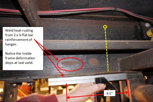
There is a small ripple on the outside under the 1/4 x 2 flat bar between the welds. See here.


This is my belief, of what happened. See if you agree. That 1/4 x 2 flat bar reinforcement helped the outside flange not bend. But there is still a ripple in it. The inside did not have the added piece and it is believed to take the blunt of the load. When a large dynamic towing load comes from a pot hole, that area behind the rear hanger is the weakest spot. The back of the camper is cantilevered off the axle hanger area. When that heavy bounce goes through the frame, the bottom flange has to resit the buckling loads. If it can't handle that load, it blows out. Bends up or down. Look how heavy the bend is right at the hanger? If the beam is going to fail, that is the mode it would fail in. The top flange is in tension.

This frame failure was a massive one. It buckled the same way. But it also bent a lot more. Bent frame

Now to the jacking. I'm pretty anal about jacking but being open minded I needed to prove to myself the jack stands did not cause this.

See here.

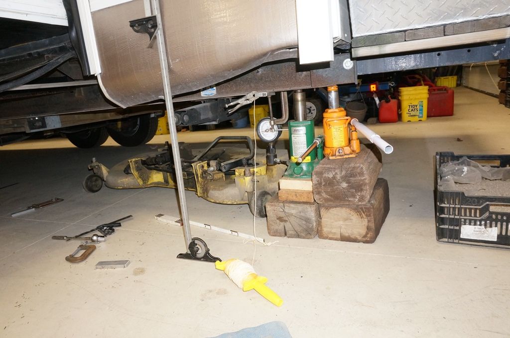
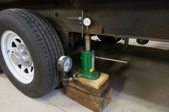
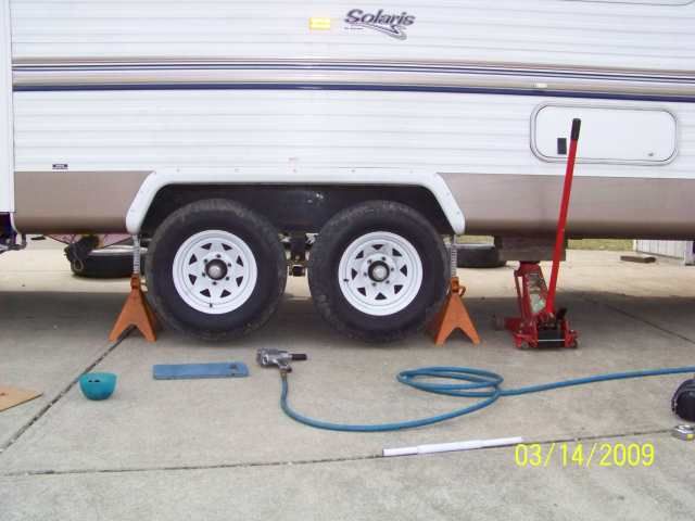
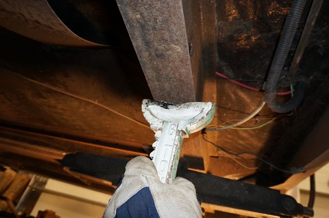
You can see where I put my floor jack, it has 2 large oak boards on top to gain height and I always make sure the jack top plate is dead center on the frame rail.


Once the tires are off the ground, I slide the jack stands in and I always use 4 stands. When I let the jack down, the front jack stand “always” touches first, then the back stand as the camper is sagging as the jack is behind the rear axle.

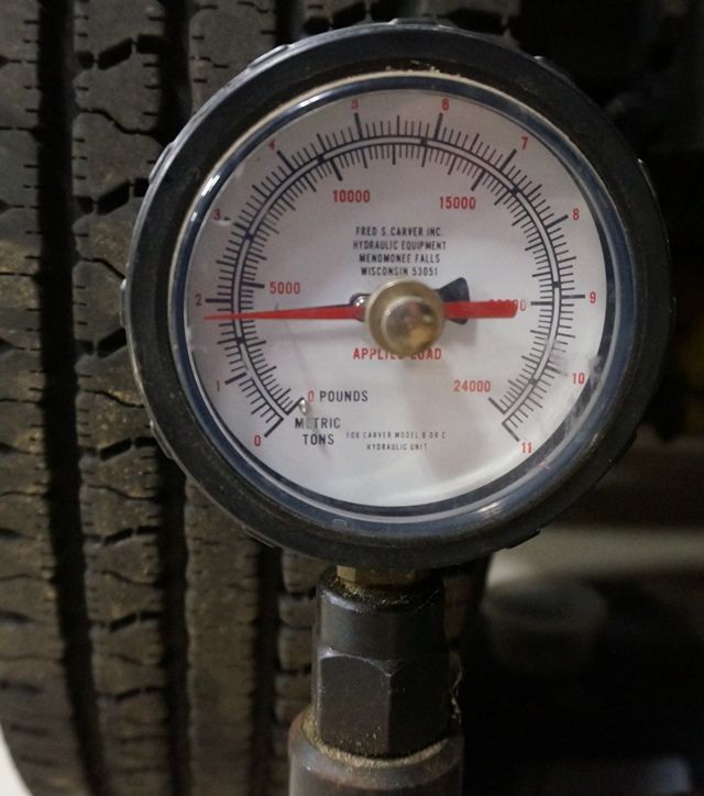
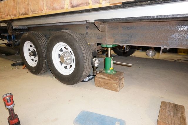
To prove I did not create this with my jack stands, I used my force jack and measured the force to lift the left side of the camper with the tires off the ground. This is not the towing weight as have all food, and freezable things out of the camper for winter but is it close to full weight.


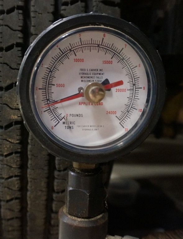
Here is the weight of this side at this jack point, 4,000lb


And here is the back side once the front jack stand touches, 2,800lb


So that rear jack stand was holding 2,800lb. That gave me a force load to start with. I could use that info to do a quick stress calculation on the lower flange to see what league the stress the lower flange might be in from and off center jack stand.

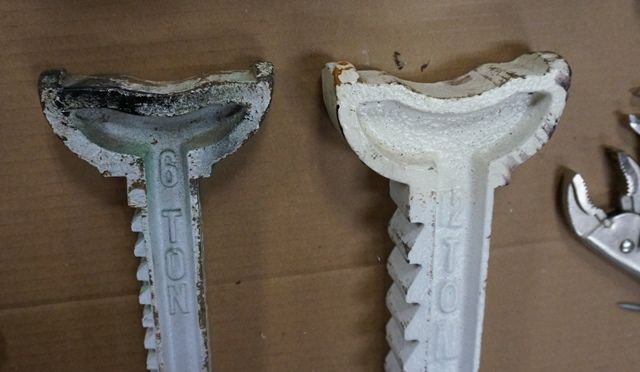
First let’s look at the jack stand and the frame. Hopefully this screen print comes out so you can see it. I have 6 ton and 12 ton jack stands. We are talking about the 6 ton one use with no plate on it. The 12 ton I have to use plates on the stand to bridge the curved depression as the curve is too wide.


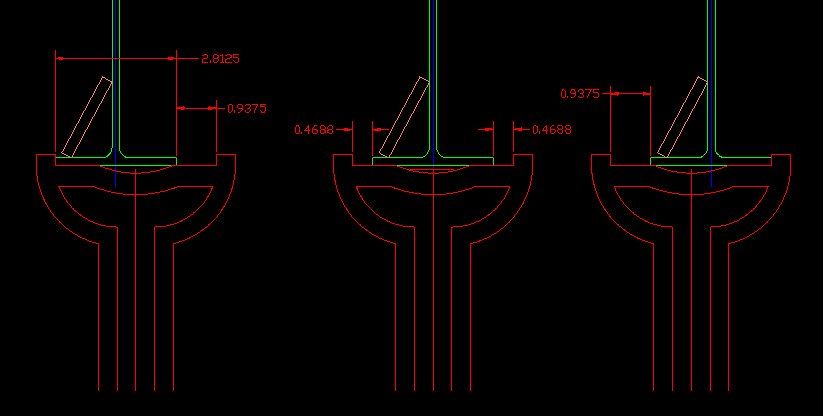
This drawing is to scale of the 6 ton jack stand arm and the frame.


On the left, is the stand arm shifted full right. See the support is under the gusseted area and there is a small amount under the inside flange.

The center image shows the stand centered. Both flanges now have contact.

On the right, the stand arm is shifted all the way to the left. In this case, the inside flange has a lot of support and the outside flange has a very small amount but still in contact.

Since this added 2” gusset was not always on the camper, I did a quick calculation based on that drawing of the far right image where most of the weight is held by the inside flange on the jack stand. Note: The left flange is still touching, just not a lot. The stress is not high enough with a jack stand load of 2,800lb to permanently deform the flange. Granted you do not want to bounce the camper on that right flange but the static load did not show it was enough to permanently bend the flange. Remember, the outside flange still touches a little and is carrying load. I “normally always” center the jack stand on both flanges have load. But even if I mess up, both side of the flange still have load on them.

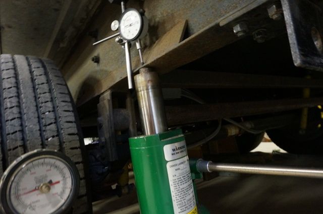
As a backup, I measured the deflection of the outside flange under the gusseted area while jacking up the camper. This is actual data from jacking up the camper, not calculated. This helps show how much added strength that gusset adds. Basically putting it, that reinforced outside flange can lift and hold the entire 4,000# of the camper and then some.

CAUTION: Do not try this at home….:rolleyes: (seriously, your camper may not handle this)

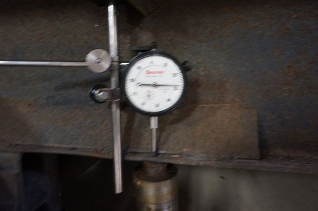
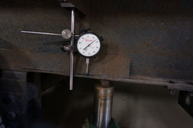
Here is the test, a dial indicator up high on the frame with the touch point on the outer flange. The force jack is placed on the very outside of the flange on purpose for this test. The most deflection potential location.


I did this twice with the jack in 2 locations. The first is to put the indicator tip on the flange “between” 2 welds and the jack under the indicator. This allows this short piece of deflect more freely. This deflected 0.028” with a full 4,000lb lift of the camper. Sorry for the out of focus pic. 0.028” is not much and nowhere near the yielding deflection point of this steel.

The next test was to place the jack right under the gusset weld but leave the indicator tip in the same location. This deflected 0.015” with a full 4,000lb lift of the entire camper. Even less.


Point in all this, the way my 6 ton jack stands and camper frame are made combined with the way I use them, it is not causing the frame damage.


To the fix, the frame is bent down 3" as measured at the end of the frame. In order to back flex it enough, I would need to chain down the frame at the hanger and lift the back of the camper above the normal straight level. I might have to go 2 to 3" above. I have concerns about that much flex in the rest of the camper. I can tell I am lifting the camper with the jack at the back wall. The rear tire contact patch to the concrete is almost gone. Thus the need to chain down the axle area. I don't think I can pop it back straight without doing other damage to the upper part of the camper.

Does this help show my point about this being load stress?

Thanks

John
2005 Ford F350 Super Duty, 4x4; 6.8L V10 with 4.10 RA, 21,000 GCWR, 11,000 GVWR, upgraded 2 1/2" Towbeast Receiver. Hitched with a 1,700# Reese HP WD, HP Dual Cam to a 2004 Sunline Solaris T310R travel trailer.

marcsbigfoot20b
Explorer
Explorer
From those pictures it almost appears that there was a tire blowout that slapped the heck out of the frame....weakening it and it started to droop.

JBarca
Nomad II
Nomad II
Doug,

Thank you very much. Just hearing the issue is out there is a help. Yes, my frame was contracted to LCI to build from Sunline specs who is now long gone. They went under in Nov. 2006. I called the local LCI plant in PA who made the frame asking for help on confirming the grade of steel. While that operation is very much smaller now, they helped me confirm the steel grade so I know what I'm dealing with.

dougrainer wrote:
Do you know if you have a LCI(Lippert) Frame?

LCI builds the chassis to the OEM engineers specs, NOT what LCI engineers it. I have seen (Master tech) dozens of LCI frames that do what yours is doing over the years. The problem is, they do NOT build the frame strong enough for the Hole cut out for the slide room. That causes the type flex you have experienced.

Usually what causes the customer to notice the problem is when they have numerous issues with the operation of the slide room. It sticks/jams/ will not go in and out correctly.

In this case, the frame bend is only at the rear hanger. The slide arm hole area shows no signs of being bent. It is true straight along the bottom of the frame rail.
But behind the rear axle hanger, there is lower flange damage.
The yellow line is the center of the bend.


Here is the outside


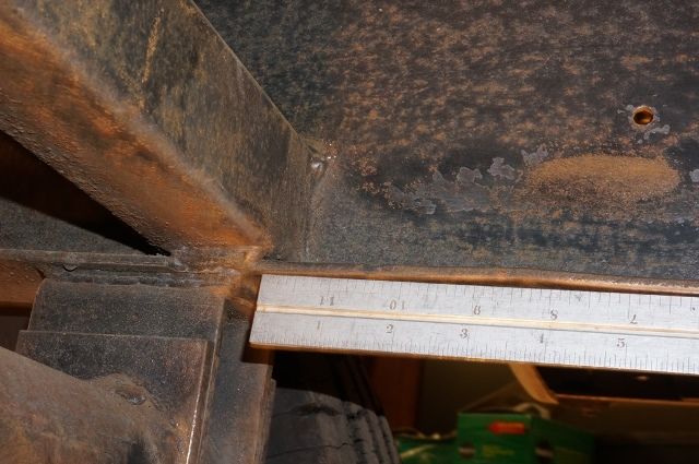
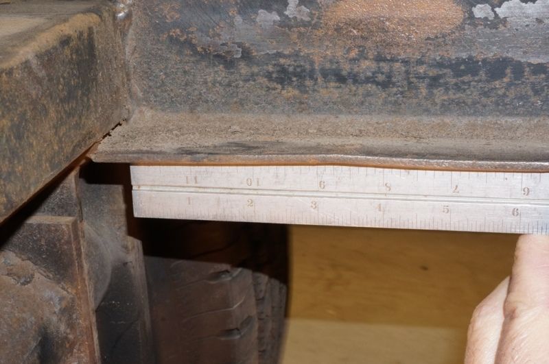
I did look at the door side, once I scraped rust off I could see it better. The door side has a small ripple in the lower flange in the same place, just this side is not yet bent. While the lower flange started to buckle, it did not bend the beam yet. (luckily) This are I can reinforce before it gets worse.

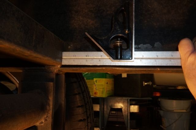
Here are pictures of the slight ripple. If you find this on your frame behind the rear axle hanger, this is the time to address it before bigger issues come over time.


At the 3 1/2" mark is the center of the ripple bump


Looking at the top


Holding a straight edge up against the rippled area so you can see it maybe a little better.


I have a plan on how to correct this, but looking for info on what has been done before.

Thanks again

John
2005 Ford F350 Super Duty, 4x4; 6.8L V10 with 4.10 RA, 21,000 GCWR, 11,000 GVWR, upgraded 2 1/2" Towbeast Receiver. Hitched with a 1,700# Reese HP WD, HP Dual Cam to a 2004 Sunline Solaris T310R travel trailer.