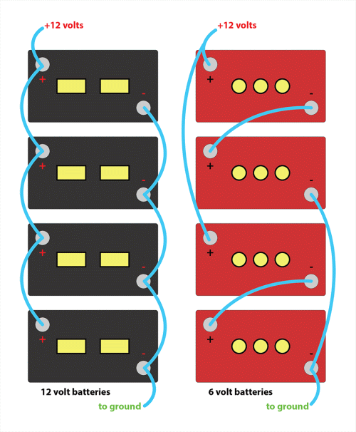
Sully2 wrote:
The proper way to wire them together is...

The math from smartgauge shows your 12v bank (their Method 1) far from ideal.Method 1
Notice that the connections to the main installation are all taken from one end, i.e. from the end battery.
The interconnecting leads will have some resistance. It will be low, but it still exists, and at the level of charge and discharge currents we see in these installations, the resistance will be significant in that it will have a measurable effect.
Typically the batteries are linked together with 35mm cable in a good installation (often much smaller in a poor installation). 35mm copper cable has a resistance of around 0.0006 Ohms per metre so the 20cm length between each battery will have a resistance of 0.00012 Ohms. This, admittedly, is close to nothing. But add onto this the 0.0002 Ohms for each connection interface (i.e. cable to crimp, crimp to battery post etc) and we find that the resistance between each battery post is around 0.0015 Ohms.
If we draw 100 amps from this battery bank we will effectively be drawing 25 amps from each battery. Or so we think.
In actual fact what we find is that more current is drawn from the bottom battery, with the current draw getting progressively less as we get towards the top of the diagram.
The effect is greater than would be expected.
Whilst this diagram looks simple, the calculation is incredibly difficult to do completely because the internal resistance of the batteries affects the outcome so much.
However look at where the load would be connected. It is clear that the power coming from the bottom battery only has to travel through the main connection leads. The power from the next battery up has to travel through the same main connection leads but in addition also has to travel through the 2 interconnecting leads to the next battery. The next battery up has to go through 4 sets of interconnecting leads. The top one has to go through 6 sets of interconnecting leads. So the top battery will be providing much less current than the bottom battery.
During charging exactly the same thing happens, the bottom battery gets charged with a higher current than the top battery.
The result is that the bottom battery is worked harder, discharged harder, charged harder. It fails earlier. The batteries are not being treated equally.
Now in all fairness, many people say "but the difference is negligible, the resistances are so small, so the effect will also be small".
The problem is that in very low resistance circuits (as we have here) huge differences in current can be produced by tiny variations in battery voltage. I'm not going to produce the calculations here because they really are quite horrific. I actually used a PC based simulator to produce these results because it is simply too time consuming to do them by hand.
Battery internal resistance = 0.02 Ohms
Interconnecting lead resistance = 0.0015 Ohms per link
Total load on batteries = 100 amps
The bottom battery provides 35.9 amps of this.
The next battery up provides 26.2 amps.
The next battery up provides 20.4 amps.
The top battery provides 17.8 amps.
So the bottom battery provides over twice the current of the top battery.
This is an enormous imbalance between the batteries. The bottom battery is being worked over twice as hard as the top battery. The effects of this are rather complex and do not mean that the life of the bottom battery will be half that of the top battery, because as the bottom battery loses capacity quicker (due to it being worked harder) the other three batteries will start to take more of the load. But the nett effect is that the battery bank, as a whole, ages much quicker than with proper balancing.
I have to be honest now and say that when I first did this calculation in about 1990 I completely refused to believe the results. The results seemed so exaggerated. So much so that I wired up a battery bank and did the experiment for real, taking real measurements. The calculations were indeed correct.


