Forum Discussion

jjrbus's avatar
jjrbus
Explorer
Oct 30, 2015

PD9145a bonding wire

I have a Progressive Dynamics PD9145A to install. I have muddled my way through most of it, but do not see a spec for the chassis bonding wire.

The directions say "Caution risk of fire. Chassis bonding wire must be a seperate wire ran directly to chassis from the Grounding Lug provided on the side of the converter. DO NOT connect output negative to chassis using same wire.

OK I understand and can do that no problem, but the wire size is not stated? It's a 45 amp converter/charger do I use a #8 wire. For the + & - because of voltage drop I need to use a #6, so should I use a # 6 to ground the case?
Jim
  • Thanks for the input, greatly appreciated. Don't go away I will likely have more questions. Jim
  • Bonding is also an appropriate term here—the chassis of the converter is being bonded to the chassis/frame of the motorhome, just as neutral is (or is not) bonded to the frame/ground system.

    The wire simply needs to be big enough to handle the maximum fault current without endangering one from fire. The current in question, here, is the output current of the converter, or 45A; so I'd go with a minimum of 8 gauge (though 10 gauge might be marginally acceptable).

    This is not required if the converter is attached to and physically a part of the metal distribution panel; it only applies to deck mount converters. (The physical attachment to the panel's chassis accomplishes the bonding for the others.)

    On my motorhome, the ground bond wire as installed by Coachmen was the same size as the output wires—all are 6 gauge for the factory 40A converter. While arguably oversized, I guess it was easier for them than stocking and dealing with another wire size just for the bonding.
  • RoyB's avatar
    RoyB
    Explorer II
    I don't know if I would call that a bonding wire. It is just a safety ground wire that grounds the chassis of the converter separately from the normal FRAME GROUND of the -12VDC cable.. I used #10 or #12 solid copper wire from local hardware store for my PD9260C converter and picked up a frame ground close to the converter. Most all of my high power chassis frames go to frame ground this way. I suspect it cuts down of RFI signals that might be generated in the units as well.

    I don't think there is any large currents from the chassis on these units unless something shorts out inside the chassis. The 12VDC cable connections will be carrying the large currents that are produced by your high wattage converter. They are just saying don't jumper over the to -12VDC post but go directly to the frame ground. Of course the -12VDC cable will eventually go to frame further down the cable path at the battery terminal area.

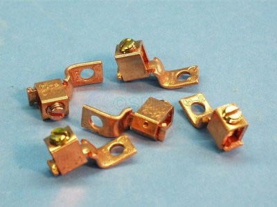
    I used one of these lug type frame ground units


    Rule of thumb is to a separate ground lug for each cable to be grounded - never double up cables anywhere...

    I of course also ran 4AWG size cables both 12VDC HOT and GROUND to the HD rotary BLUE SEA switches in the battery area.

    Bonding to me is a term used around the additional power sources of Generators and Inverters tieing the NEUTRAL and GROUND pins together to satisfy the GFCI tripping problems...

    Roy Ken
  • Bonding conductor is based on amperage. #10 would be sufficient. Larger would be better in many cases especially if you have some laying around.