Forum Discussion
Wrace
Jul 14, 2010Explorer
professor95 wrote:
OK - like I said no harm will come from the wrong wires.
Since the yellow-yellow in #2 did not work you must have the circuit in #1 with the timed motor start relay. Therefore go with yellow-red for the supra6. That should work. No idea what the time delay is - probably something like a minute. Fan starts first then when the time delay relay hits the compressor starts. This is good for a generator as it does not put the load from both motors on at one time.
In the schematic the start capacitor appears to be "optional", but your photo shows two caps, so the one in the dashed line area is there. The back capacitor is the compressor based on the wire color.
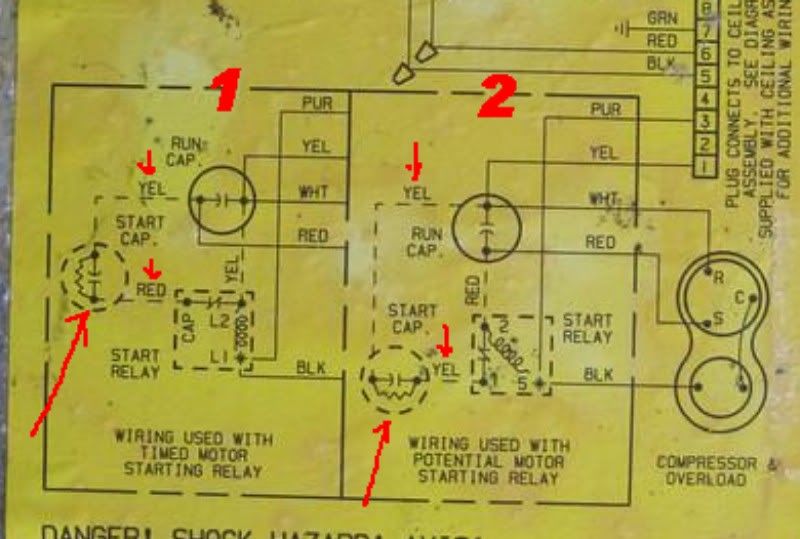


Ok thanks for the reply. I guess I'm confused now, probably always been confused. I know the picture is not the best, so it might be helpful to describe it as well. I see three capacitors in there, and based on wire color it matches up with the #2 side of the schematic.
The tall gray one which matches the wiring in the schematic labeled as the 'run capacitor' with two yellows and a white on one side, and two reds and an open on the other side. (Three spade terminals on each side of this capacitor for a total of six)
The little black one in the back matches the wiring schematic labeled 'start capacitor' with the two yellow wires going to it, and it appears to have some sort of little bridge thingy soldered across the other two terminals. (four spade terminals total on this capacitor) This is the one I tried wiring the SPP6 to today.
The little gray one in front has one brown wire and one brown wire with white stripe going to it, which matches with the schematic as the 'fan capacitor'.
I don't think this AC unit has the delayed start as it sure seems like it is starting both the fan and compressor at the same time, or if there is a delay it is more like one second or so.
Is there any harm in attempting to install the SPP6 across the run capacitor? The SPP6 has two wires, one has a regular spade connector and the other has the piggy-back spade connector (for use where there is no open connector on the capacitor). I'm not sure what terminals on the run capacitor these two wires should be connected to? I'll probably try this with alligator clips as suggested first to see if it even works.
Some other observations/questions.
When the AC will not start there is nothing when I move the AC thermostat switch to the on position. There is no clicking or sound from the AC, and no change in the generators noise/rpm. Is this just because the AC is not getting enough voltage/amperage such that it doesn't even try to start?
Yet on the occasions that it try's to start but fails to do so there is a clicking sound coming from the AC and the gen bogs way down in rpm/noise. At this point the AC is struggling and seems to be running but very sluggish and then the Honda goes into overload. This whole cycle lasts only about 10-20 second or so. What is making that clicking noise in the AC unit?
There is some sort of time-delay which occurs after a failed start attempt, or after a successful start attempt before it will make another attempt to start. In other words, I have to wait several minutes before it will make another attempt at starting when I move the thermostat switch to on. I believe it also behaves this way when plugged into shore power but I'd have to verify that. Is this delay related in any way to the delay that happens on the heat/furnance side where the burner lighting is delayed until after the fan starts?
Thanks
About Technical Issues
Having RV issues? Connect with others who have been in your shoes.24,371 PostsLatest Activity: Mar 21, 2026