Forum Discussion
professor95
Mar 28, 2011Explorer
MrRchitty wrote:
Is class back in session?
:) :) :) :) :) :) :) :) :) :) :) :) :) :) :) :)
:) :) :) :) :) :) :) :) :) :) :) :) :) :) :) :)
The students are in class waiting for the great
professor.
Sure, I would.
Randy (#2)
WOW! With an introduction like that how could anyone resist??
OK - here goes.....
>>>>>>>>>>>>>>>>>>>>>>>>>>>>>>>>>>>>>>>>>>>>>>>>>>>>>>>>>>>>>>>
An AVR is an acronym for Automatic Voltage Regulator. I've been playing around with AVR's for several years now just for the heck of it - and the opportunity to learn more about how these machines operate.
There are two types of output voltage regulation commonly in use on synchronous generators from ALL manufacturers – Asian or Domestic.
One is the AVR, which shares basic principles across the board. The other is a simple capacitor circuit as shown in the schematic of the CPE 40048 1200/1500 watt portable generator (Schematics attached below).
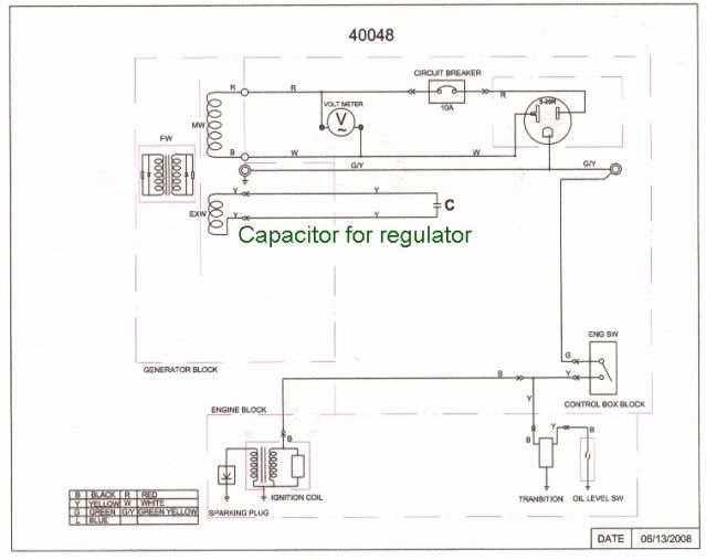
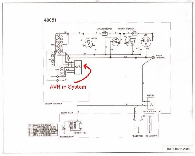
NOTE AVR IN BOTTOM SCHEMATIC REPLACES CAPACITOR IN TOP SCHEMATIC.
Interestingly enough, fellow thread contributor N9WOS recently wrote a rather long and detailed dissertation on AVR operation of his newly acquired 2000 watt Chinese synchronous generator. The posting appeared on this thread 2/11/11 at 7:42 p.m.. Page back to find the posting. It was extremely well written and contains significant detailed information on the operation of these generators and the AVR.
On my 40008, which is similar to all of the other AVR controlled Chinese generators out there, the AVR operates as follows: (See attached schematic for model 40051 above)
The exciter winding (Blue – Blue in AVR to Yellow – Yellow on generator) produces a low voltage AC signal for the AVR. The exciter winding is in the Stator, or stationary non-rotating coils of the generator (actually an alternator). This voltage is produced as the rotor begins to turn by a small amount of residual magnetism in the iron mass that is present all the time. This is the voltage that begins the self excitation process whereby some of the power produced by the generator is used to create the strong electromagnetic field needed to produce the output power.
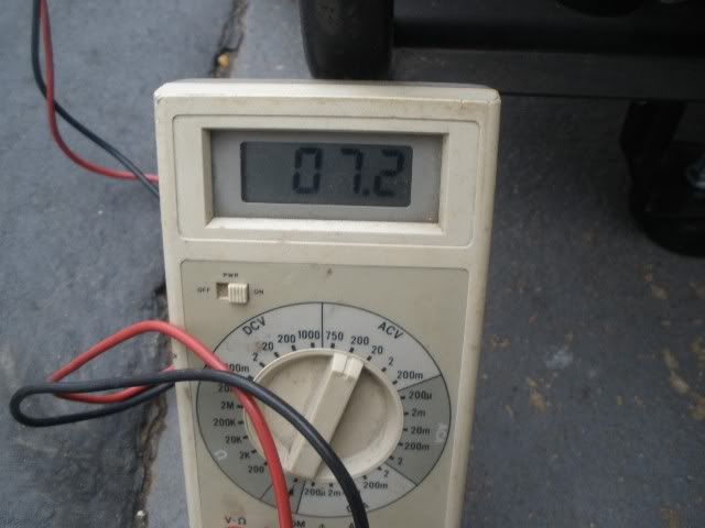
EXCITATION VOLTAGE CREATED BY RESIDUAL MAGNETISM - THIS IS WHAT GETS THE GENERATOR OUTPUT STARTED.
The voltage from the exciter winding is precision regulated (just smoke and mirrors right now - no "how" details) by the AVR and is used to excite the field windings through the brush set so that there is a stronger electromagnetic field present to produce the desired voltage in the main windings (Red-White or Red-Black). The voltage from the main windings is fed back to the AVR (Brown – Blue in the generator to Yellow-Yellow on AVR) as a reference voltage so that the AVR can keep the field excitation voltage regulated.
Yea, I know all of these connector color changes are confusing. I wish the designers had maintained the same wire colors on the AVR as the generator.
If the AVR is completely removed from the system (disconnected) there will be no excitation voltage to to the field coils via the brush set and the output voltage will be something like 4-7 VAC (Voltage is generated by residual magnetic field - see photo above).
If the AVR is present in the system and there is a failure of any component inside the AVR (i.e. Diode, FET Transistor, NPN transistors Q2-Q4 or the zenier diode) there will be no internal regulation and the field will be driven into full saturation which will produce 190 plus VAC out at the plug-in.
This can be simulated by opening one of the two wires from the main winding back to the AVR (yellow on AVR).
I have moved the AVR out of the back of the alternator on this test rig and put a switch in one of the yellow AVR leads so I can open or close the circuit.
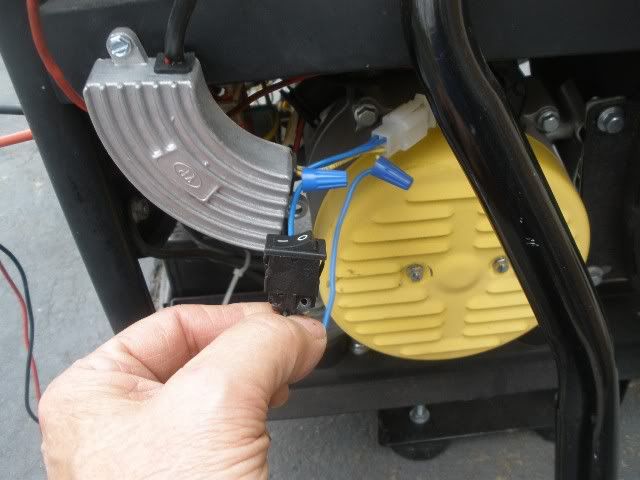
AVR MOVED TO OUTSIDE FOR ACCESS AND SWITCH ATTACHED IN MAIN WINDING FEEDBACK
As you can see from the photos, if the AVR is working properly, we have 120 VAC. If it fails, the voltage spikes to 192 VAC.
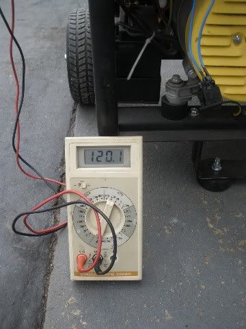
120.1 VAC READING WITH OPERATIONAL AVR
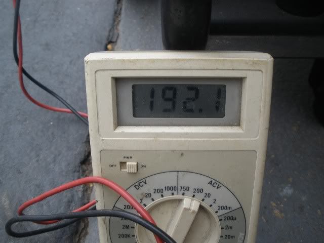
FAILED AVR CAUSES OUTPUT VOLTAGE TO REACH 192+ VAC. FAILURE SIMULATED BY OPENING SWITCH IN MAIN WINDING FEEDBACK CIRCUIT
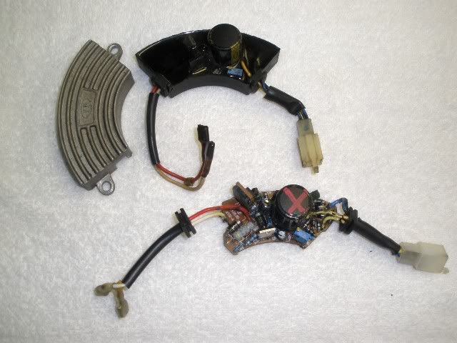
AVR TOP HAS BEEN REMOVED FROM ALUMINUM HEAT SINK/CASE SHOWING ONLY EPOXY POTTED MODULE.
BOTTOM OF PHOTO IS AVR WITH POTTING REMOVED.
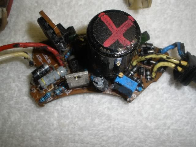
CLOSE-UP PHOTO OF UNPOTTED AVR ELECTRONICS. BLUE RECTANGULAR DEVICE WITH BRASS SCREW ON TOP IS THE USER ADJUSTABLE POTENTIOMETER FOR SETTING OUTPUT VOLTAGE
AVR failure happens without warning. It is usually associated with high temperatures that cause components to fail or high current being fed to the brush assembly to maintain maximum power output over sustained periods of time.
The AVR is mounted in the rear of the generator head, just behind the louvered cap. A fan in the front of the generator head draws cool outside air into the louvers and across the AVR. Under some operating conditions this is not enough cool air to keep the AVR at a safe operating temperature. Booster fans may be installed on the end cap or the AVR can be completely removed and remounted on a large heat sink in a cooler location. Both methods are often used when the generator is modified to work in an enclosure.
But, failure does not always occur under these conditions. The components in the AVR can become weakened then fail unexpectedly under normal operating conditions.
If it fails, the voltage spikes to 192 VAC.The problem is that if a failure can create a voltage jump from 120 VAC to 190 VAC just like “that”, any electronic component connected to the generator can be literally fried in the blink of an eye.
I have experienced three AVR failures in the past six years. The first resulted in a complete loss of output voltage, which is safe, and the last two resulted in a voltage spike. The more recent failure was, fortunately, stopped by some surge protectors with MOV’s that literally exploded, ruining the surge protectors but saving my TV, refrigerator control board and charger/converter. I did have to replace the surge protectors, but the combined cost of around $80 was small compared to the appliances that could have been ruined.
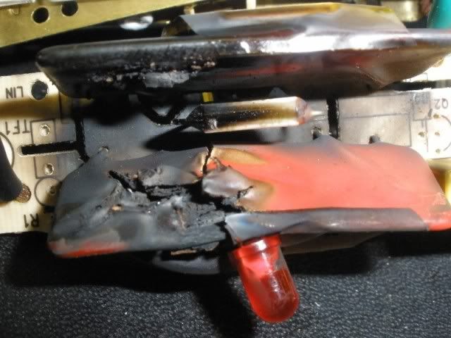
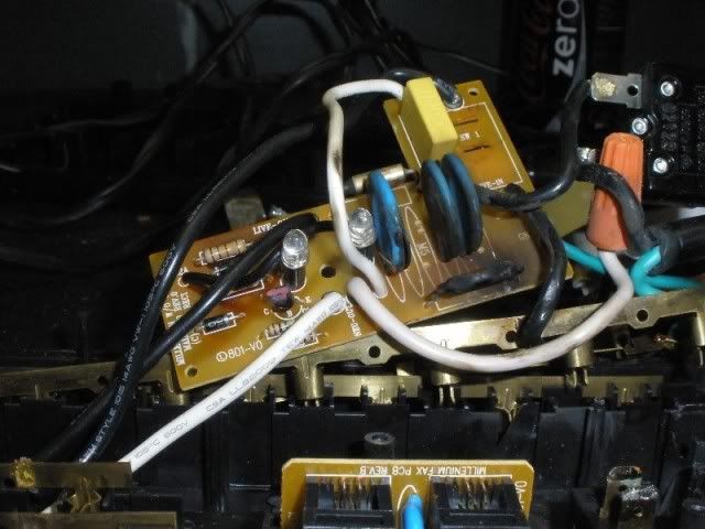
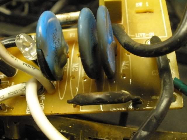
PHOTOS ABOVE WERE OF THE MOV's AND FUSEABLE COMPONENTS OF SURGE PROTECTORS DESTROYED BY 190 VAC. THEY SAVED EXPENSIVE ELECTRONICS IN MY RV BUT ALL HAD TO BE REPLACED AT A COST OF ABOUT $80.00
About two years ago CPE quietly began installing an Over Voltage Protection Module in selected models of their 120 volt generators – specifically the 46515 and the 46538. There may be other models in the CPE line-up with the OVPM, I’m just not familiar with all of the electrical designs for each model. Models with the OVPM can be identified by a device named “Transition” on the schematic that has five wires. Models with only two wires going to the Transition device will not have the OVPM. For example, the 40051 and models sold prior to the 46515 do not have the module.

MODEL 40051 WITHOUT THE OVPM
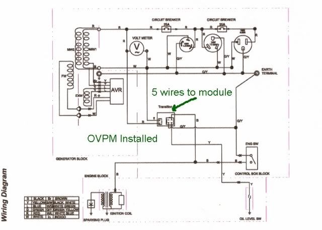
MODEL 46515 WITH THE OVPM
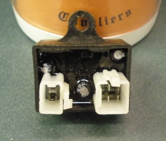
PHYSICAL APPEARANCE OF OVPM USED IN SOME CPE MODEL GENERATORS
The module monitors the output voltage. If the voltage exceeds 140 VAC for more than two continuous output cycles (1/30th of a second), the module kills the power to the ignition and the engine immediately shuts down. This response is fast enough that all but the most sensitive electronic devices are saved from destruction. Even with this, I still strongly advise the use of surge protectors on the refrigerator, converter charger and your audio/video equipment.
On the CPE model 46538 the built-in module not only kills the engine, but immediately removes power via a redesigned AVR with an extra set of wires that removes the AVR from the system. Personally, I believe the 46538 is the best of the best synchronous generator models and offers exceptional OVP features and load shedding. I will be replacing the 40008 in my fifth wheel “cave” with the 46538 in the next few weeks due to these features.
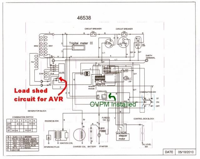
SCHEMATIC OF 46538 SHOWING OVPM AND LOAD SHED CIRCUIT ON AVR
To the best of my knowledge, no other maker of synchronous generators has an OVPM in their product line-up.
But, I have good news for owners of older generators, other manufacturers, or current CPE models without the OVPM.
SuperGen Products now has an easy to install plug-in OVPM being sold under the name of KILLAVOLT. SuperGen is a relatively new company marketing accessory products for portable generators. I have their GenTent and Lazy Man's Oil Drain. Both are pretty cool accessory items.
I recently received two KILLAVOLT modules for evaluation and testing. I kept one and sent the other to fellow thread member Jaustin, who recently had an AVR fail on his DuroPower generator. I do not know if John has had an opportunity to test his module or not (comments John?)
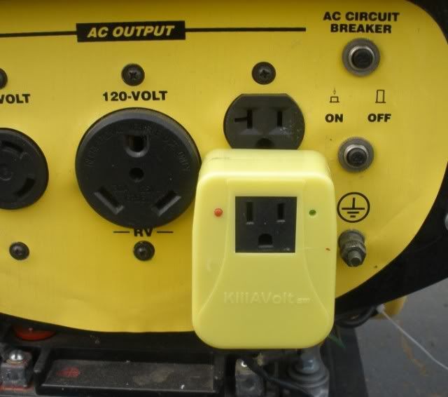
KILLAVOLT FROM SuperGen Products PLUGS INTO AN OUTLET WITH ONE WIRE TO KILL SWITCH OR LOW OIL SENSOR. SHUTS DOWN ENGINE IF AVR FAILS AND VOLTAGE SPIKES
The device plugs into an available 120 VAC outlet on the front of the generator and has a plug-in on the front of the module so you do not lose access to the outlet. There is ONE wire that comes off the bottom of the module that is attached to the yellow wire on the generator’s low oil or power down latching sensor. That’s all it takes to install. If the output voltage goes over 140 VAC the KILLAVOLT immediately senses the condition and shuts down the engine. There is a small green LED on the front to let you know the unit is operating, and an adjacent red button to push to test the unit for the correct connection and operation.
In all of my tests, the add-on module has performed flawlessly. It is a darn good insurance item for any synchronous generator that does not have a built in OVPM.
So…… That’s the AVR/OVPM story as I know it!
(EDITS ADDED: An incorrect photo and a few words out of place fixed. Amazing what a nights sleep can do.)
About Technical Issues
Having RV issues? Connect with others who have been in your shoes.24,191 PostsLatest Activity: Jan 19, 2025