Forum Discussion
westend
Dec 23, 2012Explorer
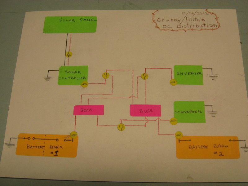
Made a bit of progress on the solar system. I pulled a bit of hair trying to figure out how I was going to distribute the 12v among the solar controller, the inverter, the converter, and the two battery banks. I posted a "Help me" thread in the "Tech issues" section of the forum and the experienced hands helped me through the design.
This is probably the second iteration of the wiring:
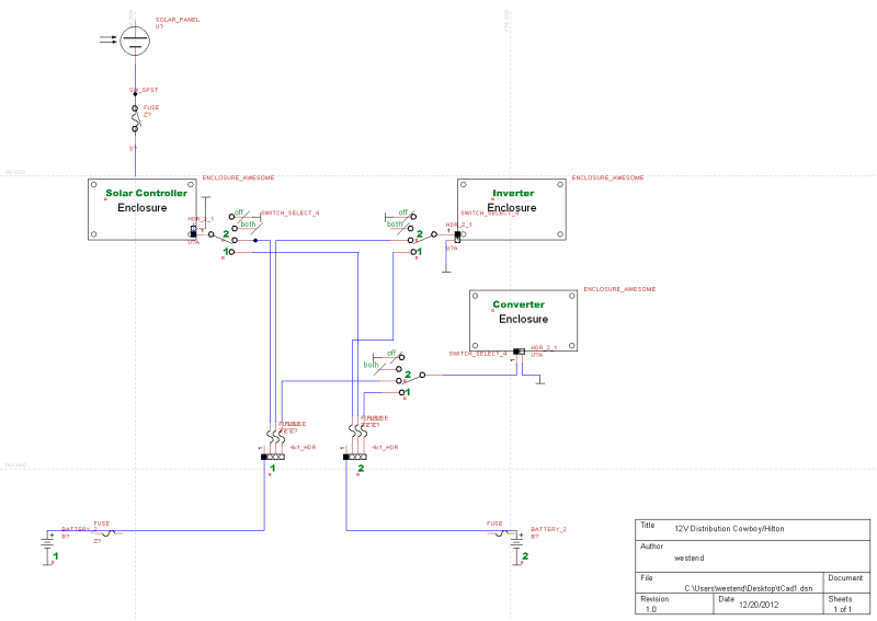
One of the guys linked me to some schematic software and I drew another plan, this time moving the fusing to the positive busses from the battery banks:
The plan is to move forward with this distribution panel as drawn except I am swapping the positions of the inverter and solar controller, it is a better physical layout with that move. Here is a mockup of the two devices and the three battery selector switches that will make everything work:
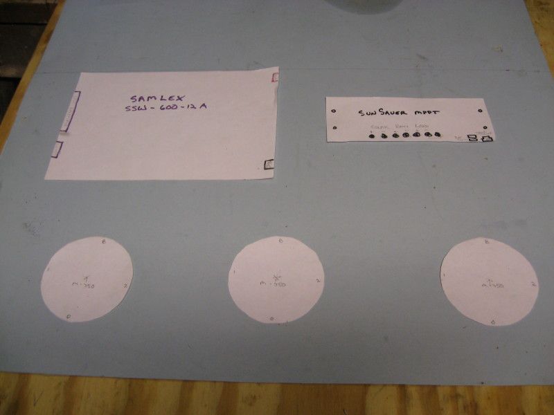
The blue paper is cut to the size of an aluminum sheet I have that will be the panel board. The round cutouts are the selector switches. To the upper left is the inverter and to the upper right is the solar controller. The converter is mounted to the floor of the compartment the distro panel will be mounted in.
I also made a combiner box for the lead-in wires from the solar panel. The combiner box will allow me to run the wire from the panel and future panels to this box. I will have #4 AWG installed from the box to the controller below. This was made from a 1 1/4" PVC LB and some lug strips from a load center I had laying around. I will be installing a water-proof fitting on the end for the 10 AWG MC4 panel wires.
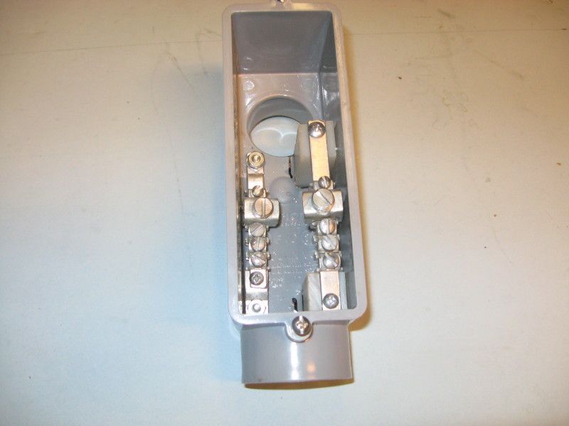
This LB will be glued up to a piece of 1 1/4" PVC conduit that is mounted on the driver's side of the Hilton, next to the window. The wire entrance will be adjacent to the shore power inlet. I chose to make the entrance on the side because I have the roof sealed and don't want a hole there, trying to wire from the ceiling to the compartment where the distribution exists would have been a nightmare, and I already have things protruding from the exterior wall.
This is probably the second iteration of the wiring:
One of the guys linked me to some schematic software and I drew another plan, this time moving the fusing to the positive busses from the battery banks:
The plan is to move forward with this distribution panel as drawn except I am swapping the positions of the inverter and solar controller, it is a better physical layout with that move. Here is a mockup of the two devices and the three battery selector switches that will make everything work:
The blue paper is cut to the size of an aluminum sheet I have that will be the panel board. The round cutouts are the selector switches. To the upper left is the inverter and to the upper right is the solar controller. The converter is mounted to the floor of the compartment the distro panel will be mounted in.
I also made a combiner box for the lead-in wires from the solar panel. The combiner box will allow me to run the wire from the panel and future panels to this box. I will have #4 AWG installed from the box to the controller below. This was made from a 1 1/4" PVC LB and some lug strips from a load center I had laying around. I will be installing a water-proof fitting on the end for the 10 AWG MC4 panel wires.
This LB will be glued up to a piece of 1 1/4" PVC conduit that is mounted on the driver's side of the Hilton, next to the window. The wire entrance will be adjacent to the shore power inlet. I chose to make the entrance on the side because I have the roof sealed and don't want a hole there, trying to wire from the ceiling to the compartment where the distribution exists would have been a nightmare, and I already have things protruding from the exterior wall.
About Travel Trailer Group
44,070 PostsLatest Activity: Aug 07, 2020