MEXICOWANDERER
Oct 31, 2014Explorer
The Old Ferroresonant MAGNATEK Converters...
These dinosaurs were 30X as common as competitive converters and were a flawed design from the word go... OEM chose the BW Magnatek units because they were the least expensive of the lot. I came a MAGNATEK OEM in 1985 solely to access the 775-2 unit and later on the 955 swithmode 55 amp charger (neither were converters).
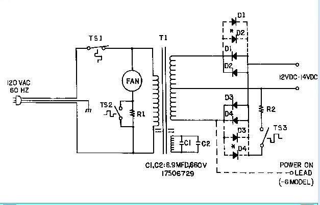
The original BW Magnatek converters "converted" incoming line voltage to "battery voltage" using a transformer and high value capacitors to achieve saturated field transformer regulation. The capacitors in theory allowed the large transformer's voltage to rise to battery voltage value. BW Magnatek's official specification for the battery charge (and rig's power supply) was 13.8 to 14.2 volts. The large and heavy transformer was a center-tapped design hence the transformer required the use of a pair of silicon TO-5 rectifiers mounted to a flat plate aluminum heat sink.
Here's where things get interesting (and sad). The converter was controlled by as yes/no DPDT 120 volt relay.
When shore power was not available the relay's contacts allowed BATTERY voltage throughput. Battery voltage flowed through the relay and onward to power the 12-volt accessories in the coach. Battery power direct except it had to flow through the relay.
Because the relay control (coil) was 120 volts, the presence or absence of 120 volt shore power determined what the converter was supposed to do.
When the relay saw 120 volts shore power, the whole picture changed. Battery power became unavailable to power the coach accessories. The converter via the relay contact switchover took it upon itself to have the capacitor controlled transformer develop ALL of the power for the coach's accessories. The coach accessories were transformer powered in their entirety.
What happened to the battery? How was it charged? A fifty watt bleed resistor tapped into the transformer coach power. it "robbed" as much as FOUR AMPERES of battery recharge potential from the capacitor regulated transformer circuit. You read right. Battery recharge was limited to four lousy amperes. And it did not matter if "shore power meant a power pedestal or a generator" the ceramic bleed resistor allowed four amperes battery charge rate (on a good day).
The problems with the BW Magnatek converter, knew no bounds. The converter was designed with low price in mind, and transformer power to coach accessories was dirtier than a Russian politician. An oscilloscope analysis showed the power to be tragic. This is one of the reasons ThinLite fluorescent lighting turned out to be near disastrous - the other being ThinLites marginal inverter circuit.
But it got worse. Ferroresonant voltage control relies utterly on the the stability of it's capacitors to be accurate to begin with and for them to retain accuracy in capacitance value as they age. Magnatek design utilized horribly substandard capacitors to begin with. The sloppy tolerances allowed a full .4 volt performance design variance according to Magnatek literature. In reality the variance was closer to .6 volt.
Worse...as the capacitors aged, voltage increased. I saw dozens and dozens of cases of "regulated" voltage in the 14.4 - 14.9 range.
Don't forget, the bleed resistor restricted amperage to around four, but when plugged in, the faulty capacitors allowed as much as 14.9 volts to appear at the battery terminals when rigs were left plugged into shore power. 24/7/365. 14.9 volts to the bypassed battery spelled disaster. And yes, when voltage climbed so did the voltage differential between the converter circuit and coach battery. Now amperage raised to 5.0 and burned out the ceramic resistor.
The "fix" obviously was to remove the converter and replace the capacitors. I did this in the 1980's and even back then, decent electrolytic capacitors cost 10-12 dollars each. Rig owners screamed foul.
13.8 is on the high end of acceptable maintenance battery float voltage at moderate air temperatures. But few of the Magnteks regulated at 13.8 volts. Most developed voltage in the 14.2 to 14.4 range when brand new, and then as they aged things went downhill from there. Voltage increase as capacitors aged.
When Magnatek was contacted by telephone their standard rhetoric was "Our converters make 13.8 volts".
After boiling a few thousand batteries dry, Magnatek introduced straight ferroresonant battery chargers. Their average 120vac, 60Hz output was 13.9 - 14.1, then Magnatek tried switch mode chargers that rendered 14.0 volts.
The end result is and was 13.8 volts got a bad rap. Not justifiable. But thousands of "victims" of so-called 13.8 volt regulation remembered only one thing. "The Magnatek converters were 13.8 volts and my batteries boiled dry". Magnatek faced hundreds of lawsuits including some proposed class action litigation.
As a result a dozen years ago, Magnatek divested itself of all peripheral manufacturing divisions. Sold them outright. Including RV converters and chargers.
And to this day, the legacy of "13.8 volts destroyed my batteries" lives on. Even newer charger and converter OEM's are skittish about 13.8 volts. While it is a tad high for my taste because of needless activity levels within a flooded battery, overcompensation to needlessly low battery float voltage levels causes other problems. Namely sulfation and stratification if left undisturbed for many months at a time.
Something to grimace about. A rig on generator power using the old Magnatek ferroresonant converter. The generator burps and surges to 70 Hz. What do you think happens to accessories in the rig when 70Hz zaps the converter? It's not pretty.
Just a little tidbit to chew on...