BoonHauler
Dec 07, 2012Explorer
Toyhauler Power System Build
I’m starting a thread here about the power system I’m installing in the trailer I’m building. Most of it will be a copy and paste from another thread I have going over at SBR.
Here’s the opening post, sorry if it’s a little windy……
The pictures are better quality over at SBR, this portion starts about half way down page twelve (12), here’s the link…....SBR Thread


Here’s the opening post, sorry if it’s a little windy……
The pictures are better quality over at SBR, this portion starts about half way down page twelve (12), here’s the link…....SBR Thread
First I wanted to start with a little background on this portion of the project. Back during the original engineering of the project it was fairly early on that I decided to drop the idea of a built in generator and run with an inverter based PV solar system as the primary means of producing power. My thinking here was that the project was geared towards boondocking and solar power would dovetail nicely with the boondocking mentality. Additionally, I just have a real hard time with the logistics of operating a generator for a primary power source, way to much noise, fuel, and maintenance for me to deal with while boondocking.
So I set out to gain as much base knowledge as I could prior to beginning the actual plans and specifications. This would allow me to integrate the power system into the frame and shell construction i.e. the battery bank and power distribution equipment.
So I fired up the computer and off I went surfing away. Here’s a few places that I found that really helped me along in gaining the knowledge that I needed to be assured the system work properly and not become some kind of white elephant that can easily happen when one takes on a project of this nature. I ran into a site called ‘Handy Bobs Blog’ with a subtitle of ‘Making off grid RV electrical systems work’ and although some out there in CyberLand think Bob’s a little to wordy, I myself feel it’s a great place to start as I did. After reading though the entire site I was convinced that I could drop the genset from my thinking and run with solar as the primary system for power production. Here’s a link to Bobs site….. http://handybobsolar.wordpress.com/
I really want to call attention to Bobs “The RV Battery Charging Puzzle”, a must read and here’s a link to that thread……http://handybobsolar.wordpress.com/t...ging-puzzle-2/
Here’s a few other sites as well…….
http://www.marxrv.com/12volt/12volt.htm
http://www.jackdanmayer.com/rv_electrical_and_solar.htm
I’ve finished up figuring out what size inverter to go with and it’s ended up kind of where I started and that’s with a 2800 watt at 120VAC. I’ve chosen Magnum Energy as they are a leading manufacturer within the renewable energy marketplace and an industry standard. The model number is the MS – 2812. This is a Pure Sine Wave inverter or sometimes called a True Sine Wave inverter. This model is an Inverter / Charger with the charging side rated at 125 Amp 12VDC. I’ll be using one of their remote panels; the ME-RC50 to provide the oversight.
Here’s their Catalog...http://lib.store.yahoo.net/lib/wind-...mREcatalog.pdf
The goal of the project is to have enough power to run my power tools and more specifically, my DeWalt compressor. It’s their model D55146, 1.6 HP, 200 PSI. http://www.dewalt.com/tools/compress...ic-d55146.aspx
My thinking here is that if I size the Inverter to handle the compressor it will be able to run the rest of the appliances I’ll be installing. I spoke with the Magnum Energy technical dept about sizing the unit and they said to figure out what the largest loads Full Load Amps (FLA) is and add 20 percent and size for that load.
Here’s where things got difficult. I contacted DeWalt to see if they could tell me what the nameplate FLA was for my model compressor and no one could tell me…I couldn’t believe it. Anyway, I decided to speak with the folks at Palo Alto Electric Motor http://paloaltoelectricmotor.com/ and we came to the conclusion it’s pushing the inverter right to its limit. My compressor will run on a 15 amp circuit but that’s grid tie and the power characteristics are different although Pure Sign Wave as well. I’m not sure I want to run this way. The fix here is most likely going to be a smaller compressor. At any rate I still get an honest 20 amp circuit with this wattage inverter and that’s a lot of power.
Next is the Solar Charge Controller and I’ve chosen to go with the Morningstar Tristar 60 Amp MPPT solar charge controller. This model is capable of handling a total of 800 watts of solar panel (12 VDC) power output. The solar charge controller is the heart of any PV solar system and I really wanted to go with an industry standard again and that’s why I chose Morningstar, they’re a really good controller. Here’s a link http://www.morningstarcorp.com/en/tristar%20mppt
Some of you might be interested in what Maximum Power Point Tracking (MPPT) technology is so here’s a link http://www.solar-electric.com/whatismppt.html
BTW, I’d really like to put a plug in for Northern Arizona Wind & Sun based in Flagstaff, AZ. They have a great website with tons of related material and a forum as well so it’s a really good one stop shop for your renewable energy needs. Their pricing is middle of the road, not the cheapest and definitely not the most expensive. I’ve chosen them to supply all of the system’s sub-components and I’ll detail all of those as the build goes forward. Here’s a link to their front page……http://www.solar-electric.com/
I would recommend that one shops around when it comes to the major items, i.e. the Inverter, Solar Charge Controller, Solar Panels, and the Batteries as they are upwards of 80 percent of the cost of the system. I decided to do a package including the Inverter and its remote panel and the solar charge controller. I found a supplier on Ebay that had a very good price on the inverter and worked with him on the two other items. Here’s a link to their Ebay page for the inverter…..http://www.ebay.com/itm/Magnum-MS281...item3a729bfda6 and here’s the online store front…..http://stores.ebay.com/exploreelectric the total for the three items was just over 2k. I’ll be calling them when I get around to purchasing the panels, that’s for sure.
I’m not installing the solar panels themselves at this point but here’s what the plan is. I’ll be utilizing six 140 watt panels and will configure them in two strings of three panels. The two strings will be placed down each side the trailers roof starting at the rear and go forward. I still need to layout this configuration but I’m fairly certain it will work and will give me the access I’ll need to setup the tilt angel and service the panels without having to worry about falling off the roof. Both strings will be independently fused & switched as to allow me more control over the input to the solar charge controller.
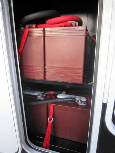
Last and the most important part of this entire system are the batteries and the battery bank. For this project the battery bank has been designed to house up to ten (10) battery group size “CG2” (Golf Cart) batteries. One of the things I learned early on was Amp Hour capacity was everything and the more the merrier. With these types of batteries the most common rating to gauge their reserve capacity is their “20 Amp Hour Rate” and these range from 205 AH up to 260 AH with the Trojan T-105 (225ah), T-125 (240ah), and the T-145 (260ah) being the industry standard and a very good reputation although as of late there’s been speculation they’ve been bought by a Chinese based company.
This type of battery is typically a ‘Flooded Lead Acid’ (FLA) and requiring servicing to maintain the acid level in each cell of the battery. I’ll be installing a ‘Flow-Rite Pro-Fill’ battery watering system to facilitate the monthly maintenance cycle of the battery bank. I’ll speak more on this subject matter once the installation begins …..here’s a link http://www.flow-rite.com/battery-watering/pro-fill
When calculating battery bank size a few items must be applied, One, the voltage/amperage. My system has been designed to operate at 12 Volts DC (12VDC) but my batteries are all 6 Volt (6VDC). I’ll be configuring my battery bank in what’s commonly called a series parallel. This means that in my case I’ll be taking two 6 volt batteries and wiring them together in series to crate 12 volts and then paralleling the sets of batteries together. So let’s say I’ll be using a 6VDC 232 AH battery. Ten times 232 equals 2320 AH at 6VDC. Being that the system will run at 12 VDC I now have to divide the total AH’s by 2 in order to get to the 12VDC amperage or 1160 AH’s at 12VDC. Next we need to understand the battery’s performance characteristics and charging profile. This is one of the areas that Handy Bob’s site covers fairly comprehensively and I won’t so you really need study up in this area. I will however talk about ‘State of Charge’ (SOC). These types of batteries have been designed to operate from 100% SOC down to 50% SOC. This is the standard factor for Deep Cycle batteries meaning they can be safely discharged down to 50% SOC before needing to be recharged.
Now that we know our battery bank can safely be discharge to 50% of capacity we now have what’s called ‘useable power’ or in my case 50% of the 1160AH capacity of the battery bank, 580 amp hours of useable capacity before the battery bank will need to be recharged.
Next I’ll go over the ‘Balancing’ of a battery bank and this is number Two in importance. If your battery bank is not properly balanced you could easily end up with a white elephant as I mentioned above. So, what happens to a battery bank that’s not balanced, in short, your batteries will not charge properly resulting in an under or over charged battery bank and a under performing power system, the White Elephant.
So, how does one balance a battery bank? One must first understand electrical resistance and conductance in electrical wiring systems. It’s a lot to comprehend so I’ll link to a Wiki page that does a lot better job of explaining things that I do, here’s the link. http://en.wikipedia.org/wiki/Electrical_resistance
In short it’s the amount of voltage drop due to the amount of resistance in a given wire size and length. Example being that a thick short wire can carry more power than a thin long wire. This is due to the resistance of the wire and is expressed in the amount of heat given off or radiated away.
It is very critical that each battery or in my case each pair of batteries have the same amount of wire resistance going to and from it. If the wire resistance is different to one battery or a pair of batteries the result of that difference will be a change in voltage / amperage to that battery/batteries resulting in either a under or over charged battery/batteries and thus an improperly charged battery bank or an un-balanced battery bank. Here’s a link to the Smart Gauge website where this is discussed in great detail….http://www.smartgauge.co.uk/batt_con.html
So to sum this all up the wire length and size to (in my case) each pair of batteries must be exactly the same as well as all the terminations. This configuration should provide for a fairly well balanced battery bank that should perform as designed.
Well there’s more to be discussed in regards to the power system and the one area I’ll be visiting in the Beta build will be the system voltage. I’m currently at 12VDC but I plan on taking a much harder look at going to 24 VDC. I think this can be done and I’ve already visited the subject matter but it was a little late in the engineering scope.
Well, that’s it for now. I’m sure I’ve forgotten to include something, just can’t think of it right now. Here are a few pics of my engineering drawings the first is the overall trailer electrical components worksheet and the second is the main power distribution system single line diagram.
Hope this helps and a lot more to come as I start installing all the devices and components……