Forum Discussion

Racorman's avatar
Racorman
Explorer
Aug 06, 2015

900 Watt Solar Panel System - Diagram and Questions

Hello all,

I’m putting the a solar system on my Class A motor home and would appreciate your thoughts on the best way to go about it.

I’ve purchased the following components:

(3) 300W Solar Panels - [Short Circuit Current 8.86 A] [Open Circuit Voltage 45.2 V] Total of 900 watts
(1) OUTBACK FM-80 CHARGE CONTROLLER
(1) MIDNIGHT COMBINER BOX
(2) 15A Breakers
(40) feet of 10 GAUGE SOLAR CABLE

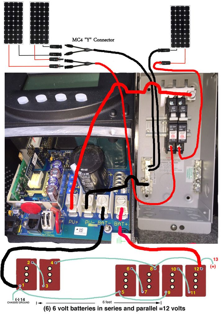
Below is a diagram of how I want to wire it.

Questions:
1. What wire gauge should I use from the COMBINER BOX to the CHARGE CONTROLLER (1 foot apart from each other)?
2. What wire gauge should I use from the CHARGE CONTROLLER to the battery bank ( about a 4 foot run)?
3. Should I just crimp the MC4 connectors to the 10 gauge wire or solder them together?
4. Any other suggestions before I start hooking up wires?

  • RoyB's avatar
    RoyB
    Explorer II
    The first thing that stood out for me was to make some of the battery cable lengths the same length even though it will not be the same distance covered.

    The RED and BLACK cables from the controller to the battery bank should be the same longer lengths. I would make these cables 4AWG size.

    The LIKE cables inside the battery bank path should be equal path lengths.

    Cables inside the battery bank 4-8, 8-12, 1-5, 5-9 should be the same longer lengths. I would make these cables 2AWG size

    Cables inside the battery bank 2-3, 6-7, 10-11 should be the same shorter lengths. I would make these cables 2AWG size.

    All of the cables short and long do not have to be the same length just the LIKE paths should be equal lengths.

    When done you will end up with three different battery cables group lengths being the two cables coming from the solar controller one length, Inside the battery bank you will have four longer group lengths and three shorter group lengths.

    The idea is that all battery groups get fed by the same amount of current coming from the combined solar panels when being charged. Otherwise some batteries will not charge up to the same level and may affect the overall BATTERY OUTPUT when being used. Eventually will do some harm to certain battery groups...

    I would make the cables feeding the 12VDC Distribution Panel where all of your fuses circuits are and frame ground connections at least 4AWG size. Some may want to see these at 2AWG size.

    These 6VDC Batteries can produce some serious DC AMPS... The cabling outside the battery bank should be protected with in-line FUSES or auto circuit breakers.

    Just my observations - I'm sure others will have different ideas...
    Roy Ken
  • Racorman

    I'm jealous! Nice looking set up!
    I live near you and am looking for panels for my new rig. Where did you get them?

    Thanks
    Bill
  • Why use mc4 connectors?

    Add them as close to the panels as you can. Crimp and solder.

    Why not just one larger breaker?
  • 1. 2 Gauge (overkill but you are already using it for step 2)
    2. 2 Gauge
    3. I am always a fan of soldering.
    4. You have no isolation between the chassis and coach batteries. The batteries are of a different type. You will drain the chassis batteries while camping and may not be able to start the coach, let alone damage the batteries due to the constant discharging during dry camping.
  • zman-az wrote:

    4. You have no isolation between the chassis and coach batteries. The batteries are of a different type. You will drain the chassis batteries while camping and may not be able to start the coach, let alone damage the batteries due to the constant discharging during dry camping.


    The battery bank shown (6) 6v batteries = 12volt are dedicated to the coach. I moved the chassis battery from mid coach to a new battery tray next to the engine (Triton® V10 gas engine). I don't plan on using solar to charge the chassis battery.

    Thanks
  • Fishbreath wrote:
    Racorman

    I'm jealous! Nice looking set up!
    I live near you and am looking for panels for my new rig. Where did you get them?

    Thanks
    Bill


    Hi Bill,

    I went over the hill to Campbell to ML Solar http://www.mlsolar.com/
    (408)583-8101 Monday-Friday 8:30-4:30 PST
    1190 Dell Avenue Suite D
    Campbell CA 95008

    Best prices and very helpful in getting me set up. Ask for the owner..... Danny
    Tell him Howard recommended him. ;)
  • Also, do I need to put an inline fuse between the controller and the batteries? If so, what size fuse?
  • Racorman wrote:
    Also, do I need to put an inline fuse between the controller and the batteries? If so, what size fuse?


    900 watts? Max that you could \get through there is about 90 amps, so a 100 amp fuse will have you covered. #4 wire is max 100 amp fuse. I guess it depends on the wire. If you are using #6 wire, then 60 amp fuse is all it is rated at.

    Good luck,

    Fred.
  • Yes. Fuse to protect the wire as close to the battery as possible. I chose to fuse on the positive.

    Racorman wrote:
    Also, do I need to put an inline fuse between the controller and the batteries? If so, what size fuse?


  • RoyB wrote:
    The first thing that stood out for me was to make some of the battery cable lengths the same length even though it will not be the same distance covered.

    The LIKE cables inside the battery bank path should be equal path lengths.

    Cables inside the battery bank 4-8, 8-12, 1-5, 5-9 should be the same longer lengths. I would make these cables 2AWG size

    Cables inside the battery bank 2-3, 6-7, 10-11 should be the same shorter lengths. I would make these cables 2AWG size.

    All of the cables short and long do not have to be the same length just the LIKE paths should be equal lengths.

    When done you will end up with three different battery cables group lengths being the two cables coming from the solar controller one length, Inside the battery bank you will have four longer group lengths and three shorter group lengths.

    The idea is that all battery groups get fed by the same amount of current coming from the combined solar panels when being charged. Otherwise some batteries will not charge up to the same level and may affect the overall BATTERY OUTPUT when being used. Eventually will do some harm to certain battery groups...

    I would make the cables feeding the 12VDC Distribution Panel where all of your fuses circuits are and frame ground connections at least 4AWG size. Some may want to see these at 2AWG size....
    Roy Ken


    Roy,

    Thanks for your recommendations..... but I've already put the battery system together. The one set of 6volt batteries to the left side of the diagram are about 6 feet from the other (4) 6 volt batteries. I had to build a battery tray for this extra set.

    Cable 1-5 and 4-8 are each about 5 feet in length. 5-9 and 8-12 are each about 16 inches in length. Purchasing (2) more #2 cables each 5 feet to replace 5-9 and 8-12 is pricey. You say eventually the different length cables will do some harm to certain battery groups. How bad might this be, 1%, 0.1%, 0.001% or really bad? The batteries are all hooked up and seem to work very well. Should I really worry about leaving things as they are, or invest in some new cables?

    I have not done the solar panel wiring yet.

    Again, thanks for your thoughts.