Mrekim,
I did some investigating today to better explain the DC effect verses No DC.
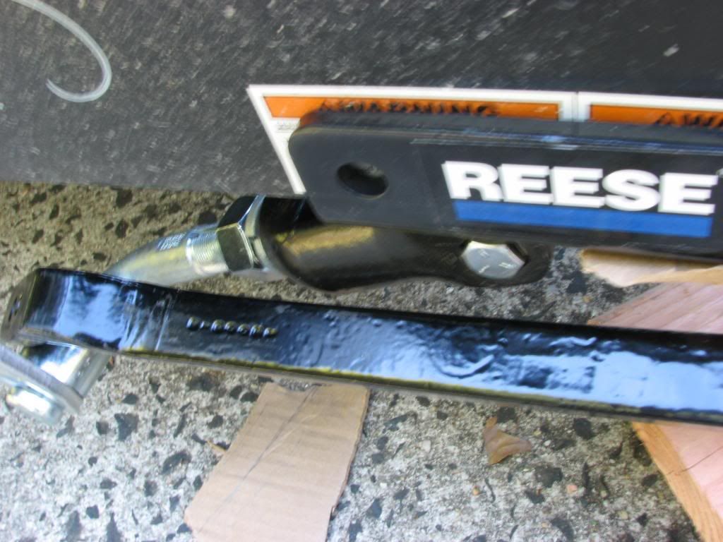
First I want to correct an error. The DC chain plate consumes 3.84” of chain length, not 3” like I stated yesterday. Had a bad measurement. I will fix the prior post. See here. Note: This is the 2007 vintage chain with 9 links next to my 2003 vintage with 11 links.
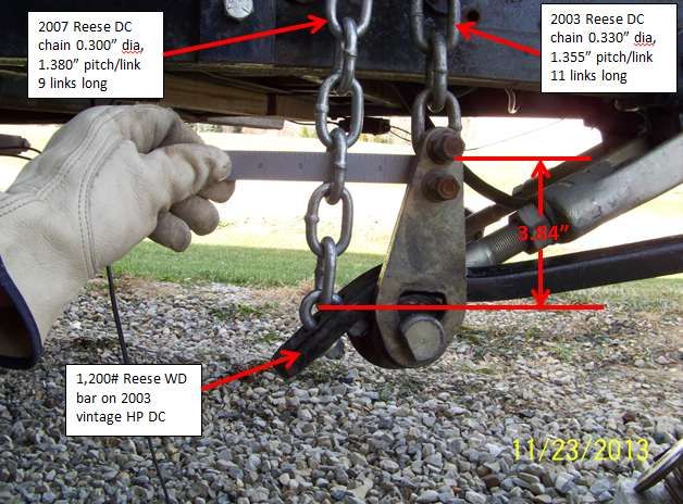
Since you changed from 1,200 to 800# bars, I cannot use that 3.84” as a chain preload change from the 1,200# WD bar.
Now to the bending snap up. A comment was brought up by Campin LI that is a good question.
Campin LI wrote:
Has anyone ever reported having a bent snap bracket when not using dual cam with Reese WDH? I am not on the forum that often but I have never read about one. Based on that, I would lean toward dual cam having something to do with bent snap bracket.
While it might be a stretch to say that a snap up has not ever bent that is not on a DC, as far as RV net goes, it begs the question, does the DC create more loading on the snap up in turns then the non DC WD setup? After what I found today, I would now say, Yes, the DC does create a larger load on one side of the A frame as compared to a non DC hitch. The outside turn WD chain increases in load more then the pendulum swing of a chain of a non DC while on level ground and even higher forces in the chain when compound angle turns occur between the TV and TT.
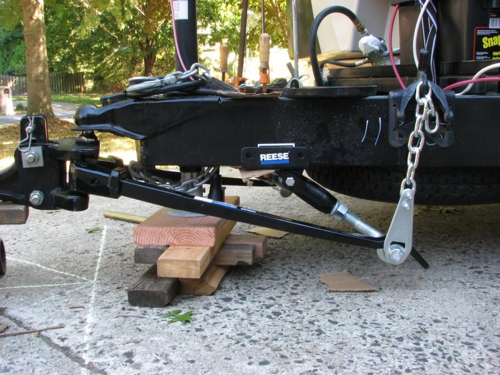
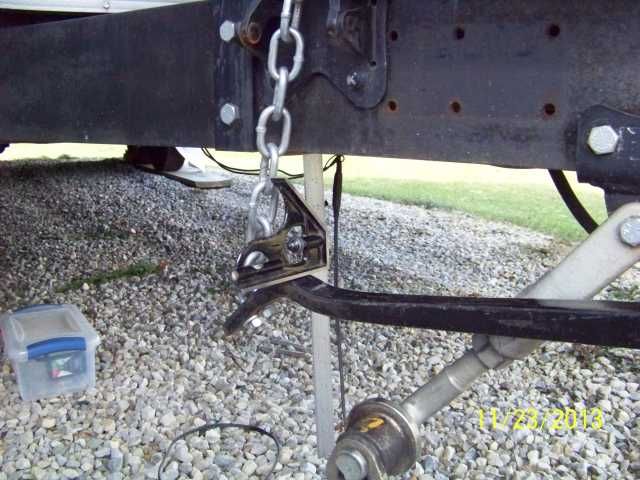
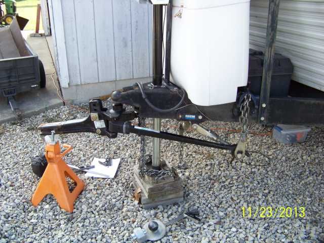
Here is what I found on the non DC WD setup. If it was not so cold out today, 25F and wind, I would of redid this on my flat deck trailer which is setup for this. Instead I mocked it up on the camper. This test is “only” if the TV and TT are on even ground.
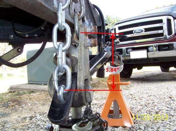
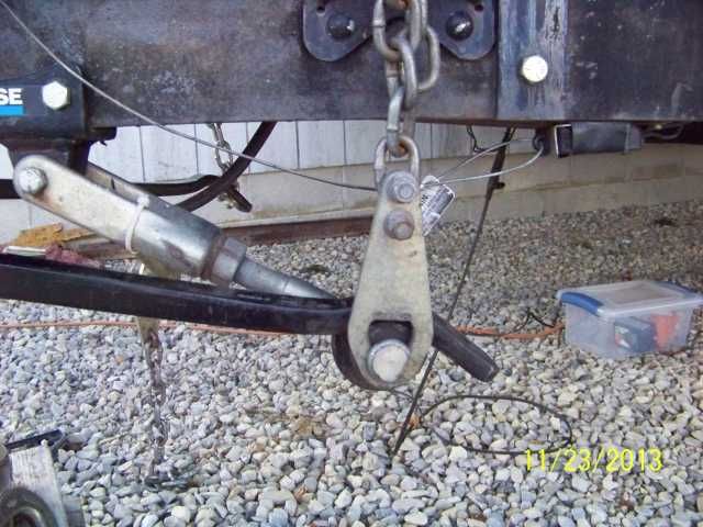
Here is a side view and how I measured the end of the WD bar movement. Since my snap up is bolted on and set for my DC, the chain is on an angle. While not normal, it does not change the gross outcome of the test.
I measured the distance between the top of the WD bar to the bottom of the A frame. Intent was to see the if there is a large or small of WD bar rise or lower occurring for different degrees of turning. This is an easy and accurate method of measuring.
I did this measurement for 0 deg, 15 deg, 30 deg and a 45 deg turn. We will later compare this to the DC. This is on 9 chain links using a 1.380” chain pitch.
Here is the data:
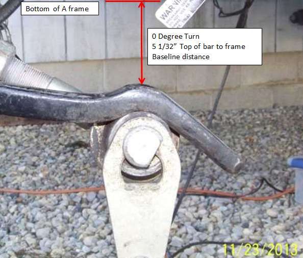
0 deg turn: 4 7/16”, Base line dim.
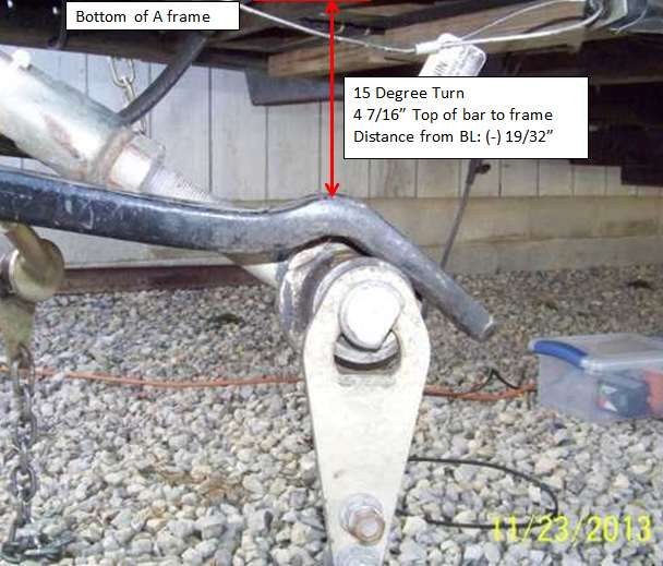
15 deg turn: 4 15/32”, 1/32” less than baseline
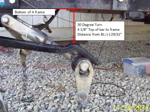
30 deg turn: 4 17/32, 3/32” more than baseline
45 deg turn: 4 14/32”, 3/32” more than baseline
Since the chain was not plumb, the WD bar distance was not centered around 0 deg turn. The point is, there is only approx 1/8” of WD load change on the end of the WD bar when running 9 links under tension. This will get larger when the number of links is less as the arc of the swinging chain will create more movement. I believe there is little difference between the 30 and 45 deg turn, believed to be mainly due to the arc of the hitch head not pulling the bar as far. I was only eye balling this within 1/64” to 1/32” and there is a little error in the dimension.
So that we can see what this amount of turn is, see here. We will repeat this for the DC. (this was setup with a protractor)
O deg turn. Straight ahead.
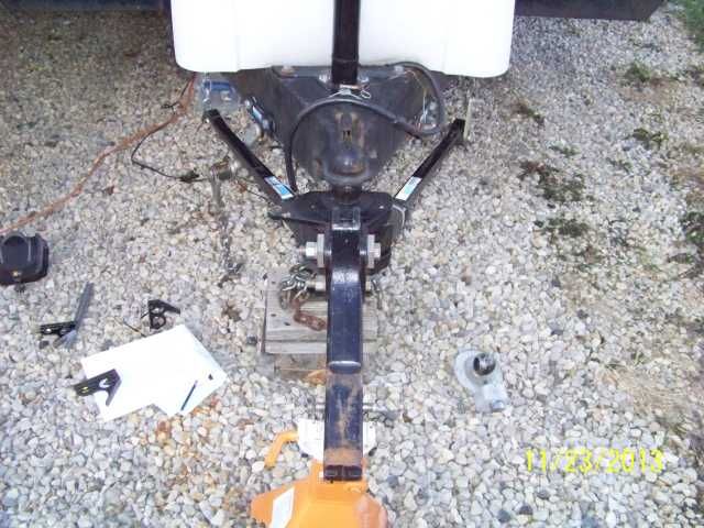
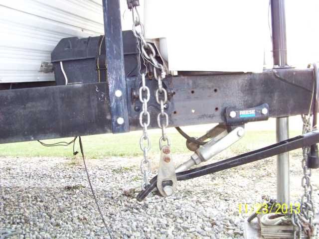
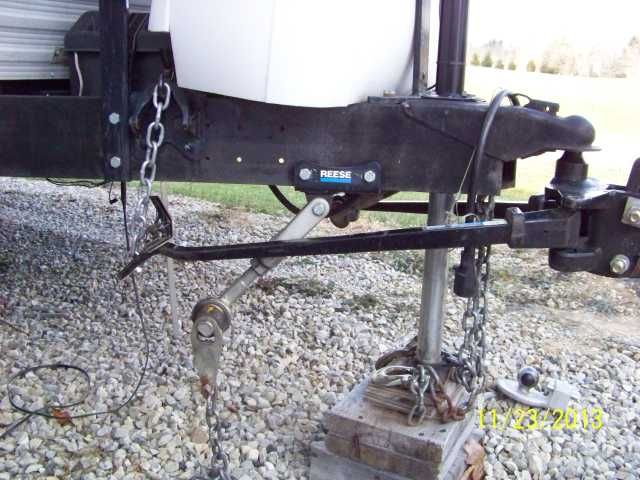
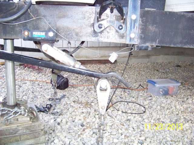
Now the DC setup. A side view
I was able to tighten the cam arm so the arm will not move and we can see the bar lifting on the cam. And I hook the chain back up each time when I move the shank, take the dimension, then take it back off the snap up to take a pic. Here is a 0 deg turn. I measured the bar movement the same as I did with non DC, using the combination square.
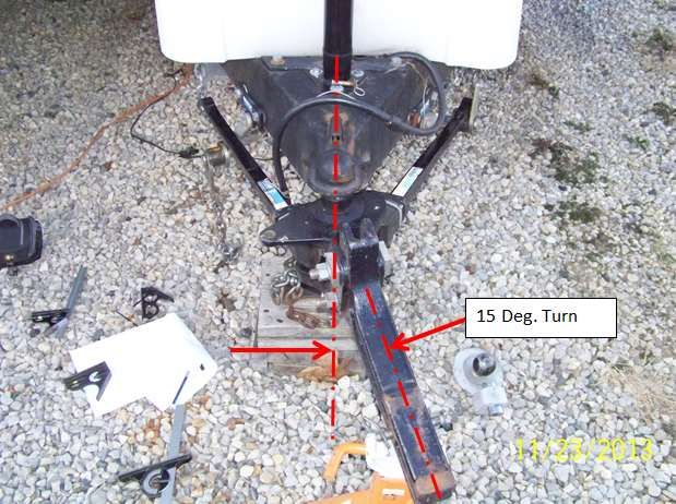
15 degrees. Notice at 15 deg. there is 19/32” WD bar load as opposed the 1/32” movement on non DC chain swing.
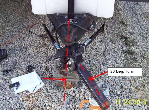
30 degrees.
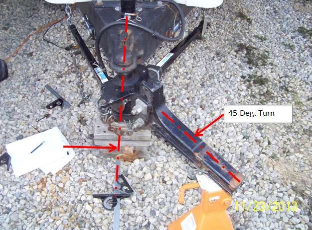
And 45 degree.
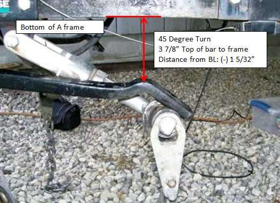
What we see is, on even ground there is 1 5/32” worth of WD bar preload on a 45 degree of turn where there is an 1/8” on the non DC chain swing. Since the chain pitch links are 1.355 or 1.380” pending vintage, that is almost 1 entire chain link more of WD force increase on the one side.
The outside turn is more aggressive then the inside turn. On level ground 20 degrees of turn is about all the chain force increase you will get due to the shape of the WD bar V. This is 20 deg.
Now changing to the towing day the TT frame bent. Odds are high you did a 30 to 45 degree turn making that 90 degree turn from the side street. We know it was a compound angle turn with a level of back flex in the hitch and possibly the back of the truck bounced creating an impact shock.
To make it worse, odds are very high the inside WD bar completely unloaded to 0 chain force because of the hitch head tilted on uneven ground. Now the outside bar is the taking all the load it can give.
After now seeing where most all these forces can add up from, quantifying all of them is not a straight forward calculation. We can create the chain load on level ground straight ahead and the WD adjusted to return the front of the EX to unhitched weight. We can estimate the outside turn load increase from a 45 deg turn by the amount of WD bar movement from today’s tests on an assumed WD bar spring constant. We can maybe make a big picture estimation (WAG) on the hitch head tilt and what it adds to the compound angle turn. Then there is the back flex and worse, the possible truck bounce impact. Short of having a load cell on the chain itself, this one is a tuffy….
I hoping Ron can see something I’m missing. Hey Ron, thoughts?
What happened with your hitch in your turn is no different than what others with DC’s experience all the time. Remember mine is 1,600# TW on 1,700# WD bars. The DC hitch has these attributes to it and now may understand them better. This leaves the TT frame. Your style A frame does not like high point loads presented to the side of it. The use of added plates to help spread the load out is a prudent step from my point of view.
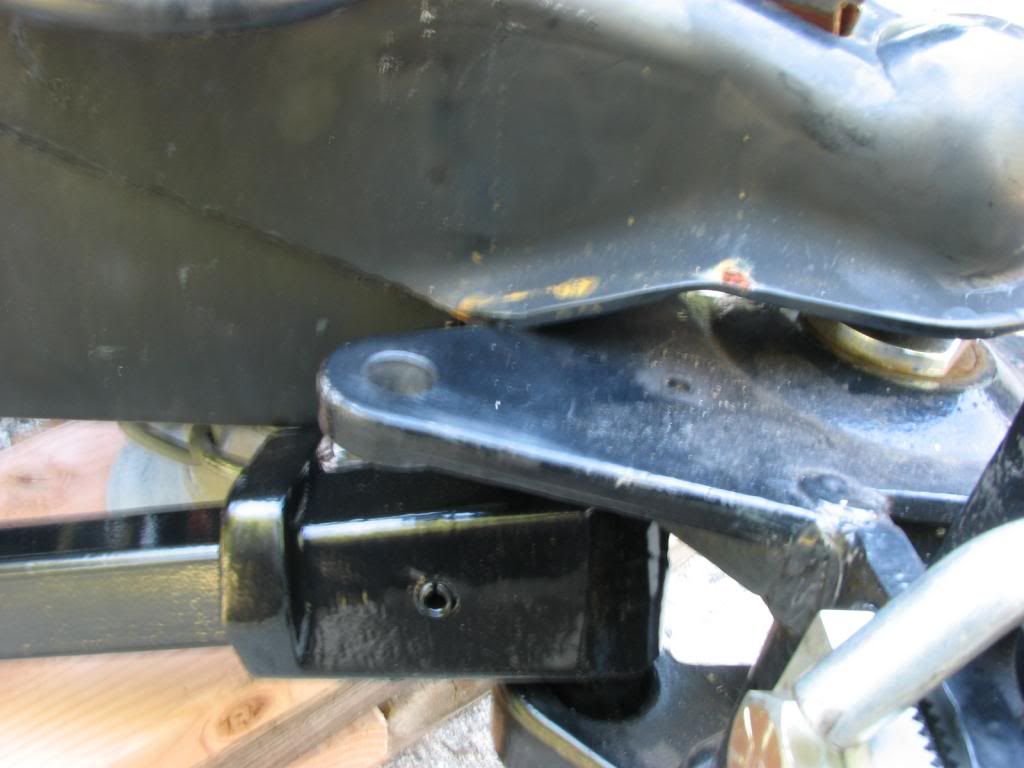
In reviewing all this, I would expect that the high chain force in that turn buckled the frame at the setscrew of the snap up first. Then snap up then bent. Once the snap up bent, the chain hangs out a lot farther and pulls on the DC arm in a twisting motion. When the high chain force that bent the snap up pinch bolt area developed, the increased chain force created very high friction in the DC. As the turn progressed the friction dragging force of the WD bar agasint the DC went up very high and traveled up the cam arm to the A frame. Since the cam arm was being twisted by the outward hanging chain, the combo of both them bent the DC frame plate mounting area of the A frame resisting the load. This may have been aggravated by the flat washers behind it creating a localized point load.
(Edited 11-25-13 fixed mixed up words:o)
That is my take as of right now on how this all came about. You are on the right track on how to help the sides from further buckling. I’ll send some thoughts on your no weld option.
Hope this all helps.
John