Turn on suggestions
Auto-suggest helps you quickly narrow down your search results by suggesting possible matches as you type.
Showing results for
- Good Sam Community
- Groups
- Travel Trailer Group
- Forum
- Re: Slide blows fuze
Options
- Subscribe to RSS Feed
- Mark Topic as New
- Mark Topic as Read
- Float this Topic for Current User
- Bookmark
- Subscribe
- Mute
- Printer Friendly Page
Slide blows fuze
Options
- Mark as New
- Bookmark
- Subscribe
- Mute
- Subscribe to RSS Feed
- Permalink
- Report Inappropriate Content
Mar-25-2017 12:19 PM
2017 Forest River Surveyor RKS251. This should be under warranty, but have to haul it 100 miles to repair. So, am searching for help with my problem. The slide (u booth) blows the fuse when being towed. It has happened three times just getting it home from the dealer. Each time the slide works good when parked. Either with the harness hooked to the tow vehicle or on 110v power, or on battery only. I retract the slide before leaving, and when we get to destination the slide fuse is blown and needs replacing. I can extend and retract the slide multiple times when parked, but towing it causes the fuse to blow. Can't find a schematic for our unit so have no idea about the wiring. I don't think there is any connection, but the LED awning lights would not work when we made our first stop. They were not checked during the walk thru because there was not enough room to deploy the awning. The fuse in the panel was not tripped, but found an inline fuse behind the lighted switch that was blown, a 3 amp one, replaced and all is well with the led lights. To me this sounds like a short or bad switch, but does not make sense. Wouldn't the slide switch have to be either in extend or retract position for the fuse to be blown? Thanks JH
27 REPLIES 27
Options
- Mark as New
- Bookmark
- Subscribe
- Mute
- Subscribe to RSS Feed
- Permalink
- Report Inappropriate Content
May-04-2017 08:58 AM
Follow Up
Isolated the hot wires from the slide rocker switch. It still blew the fuse when I towed down to the Salem OR area. This tells me the ground is between the electric panel and the rocker switch. Hooked the wires back up and replaced the fuse (5th time). Slide worked properly while in the rv park. Forgot to pull the fuse when we went on down towards Reedsport.But when parked the slide still worked properly. Had not blown the fuse.Figured that it must have finally arched away enough of the grounding area, so as to not touch any more. This kinda makes sense to me if it is grounding on aluminum. Kinda like fixed itself. Towed on to the Florence area of OR and slide still deployed after towing. But when I retracted the slide it blew the fuse just at the end of the retraction. Hummm? Never done that before. Was wondering if that circuit had a minor grounding episode, but not enough to blow the fuse, just weaken it a bit. But, it had deployed ok, just blew it on the retraction. Came on home with the blown fuse and parked it. Replaced the fuse and it is back to working properly. I don't think it is a good situation, knowing there is the potential for a grounding event, but short of tearing out a bunch of wall/floor what is the alternative? If it stops altogether that is one thing, but if it keeps on occasionally blowing the fuse that is another thing. At this point a dealer probably would not be able to duplicate the problem. While in Salem I went to Highway RV and asked the service rep what she thought,
"Well, a 40 amp fuse seems to make a difference for some owners". Well, the main fuse is a 40 amp one. Guess it could arc longer and bigger with one of those. Not even going to a 40 amper.
Options
- Mark as New
- Bookmark
- Subscribe
- Mute
- Subscribe to RSS Feed
- Permalink
- Report Inappropriate Content
Apr-08-2017 11:02 AM
Awwwh, I understand. Good idea, will tape the ends of the reds before our next outing, to eliminate the switch as a culprit. Might do the same for the white ground wires also. Found out I was making an incorrect assumption about the wire routing. Was just checking the panel to see what would be involved in removing it to check the wires behind it. Thru a small crack at the bottom I could see all the wires going down under the floor, so the wires run in the basement past the rear door and then into the wall and up to where they can enter the upper cabinet space for all the switches. Seems that all the wires would have to be removed from their fuses or breakers to remove the panel. Would have to tag each one to make sure it is returned to it's rightful place. I suppose the basement makes the wires more accessible, but still a major pain to remove the plastic covering, insulation etc. to gain access. Think I will just keep two lengths of wire around so that I can bypass the shorted area if they should ever get welded together. That is when it would have to be fixed, for sure. Tempted to haul it 1250 miles back to Moreno Valley to let the dealer have the honor of fixing it. Nothing like spite.
Options
- Mark as New
- Bookmark
- Subscribe
- Mute
- Subscribe to RSS Feed
- Permalink
- Report Inappropriate Content
Apr-05-2017 12:47 AM
Sorry, I realized I wasn't clear in my last post. I meant to say try disconnecting the red wires from the switch and tape over the ends and leave them off before trying another trip with the fuse installed, to completely eliminate the switch as a possible short. Then all that remains is the red wire back to the fuse box.
You're correct that you can save the fuse by pulling it before travel, but what I'm saying may happen is if the short remains after you stop, the fuse will blow when you plug it in.
One more thought: Is there anything else on that same fuse that could have an issue or is only the slide non-functional with it pulled?
And another thought: Since the fuse is at the bottom of the box, is there any chance a bare ground (wire or sheet metal) is near the fuse or terminal where the red wire connects at the fuse box?
Options
- Mark as New
- Bookmark
- Subscribe
- Mute
- Subscribe to RSS Feed
- Permalink
- Report Inappropriate Content
Apr-04-2017 07:42 PM
I'll check and see if I can find any evidence of sparking on the red and white leads. I may be able to find some shrink tubing that I can put over the bare ends and see if I can get it shrunk down. The switch is about 30 inches in front of the slide fuse and 5 feet above it. I guess in an emergency I could run a wire thru the living space to the switch. So far this incidental grounding has never happen while stopped. So, I kinda thought if the fuse was pulled during tow times then there should be no shorting out, if there is no voltage on the wire. Only problem is, this fuse is at the very bottom of the fuses and the cover makes it awkward to get at. But I can relieve the cover to allow easier access. Think I'll see what a dealer says about fixing it, before hauling it to them. Thanks for the help, advice, info. Feel like I learned a bunch.
Options
- Mark as New
- Bookmark
- Subscribe
- Mute
- Subscribe to RSS Feed
- Permalink
- Report Inappropriate Content
Apr-04-2017 06:52 PM
You got it figured out correctly. Power feeds to the switch top and bottom in forward and reversed polarity then the switch just picks which polarity to send to the motor.
Pulling the fuse won't hurt but eventually you may find the power wire shorted permanently and won't be able to move the slide. Is there any way to run a new wire from the fuse box to the switch? At the very less I would carry a spare length of wire that you may need to use to power the slide by jumpering to the switch, in the event that you get that permanent short.
You could try pulling the red wires off the switch and taping them up. There's a very small chance that the switch itself is failing in a way that causes one pin to connect to the red and white on one same side at the same time. This would definitely blow the fuse. Again, very unlikely unless one or more of the pins are loose in the switch housing and can fall into the contact inside.
Options
- Mark as New
- Bookmark
- Subscribe
- Mute
- Subscribe to RSS Feed
- Permalink
- Report Inappropriate Content
Apr-04-2017 08:44 AM
All of the wires that I saw, associated with the slide motor rocker switch, were of a heavier gauge than any of the other wires to any of other switches. I previously estimated that they were 10 gauge stranded. If I could get to the slide motor easily it would be interesting to see just how many wires go to it. Any way, the problem is the intermittent short that occurs while towing. The wiring behind the switch looks to be in good shape with no crimps or excess insulation removed. Kinda tough to check it when it routes thru the ceiling. The best I can do is check the back of the power panel and the route they wires take up past the refrigerator. If the problem is located in a spot that is not easily accessible, what would be the danger of just pulling the slide fuse when ever we tow? Or is there a breaker type fuse for the 12 volt system that could be used?
Options
- Mark as New
- Bookmark
- Subscribe
- Mute
- Subscribe to RSS Feed
- Permalink
- Report Inappropriate Content
Apr-03-2017 05:17 AM
right. On the other question, there is no "best wiring by going to the motor first.... the electricity has to flow thru the whole wire circuit one way or the other. A better "circuit design" would be to run both wires (= and +) to the motor area and have a "relay / control" circuit right there that your slide switch "talks to"... then the wiring at the motor would likely be one heavy gauge and the control / switch wiring would be a lighter gauge. This maybe the setup if there is indeed more than 2 wires going to the motor / controller.
Options
- Mark as New
- Bookmark
- Subscribe
- Mute
- Subscribe to RSS Feed
- Permalink
- Report Inappropriate Content
Apr-02-2017 05:44 PM
wnjj: That is exactly what it appears that the switch does. Before testing today I checked the voltage at the battery and at the electric fuse/breaker panel. The voltage was the same, 13.22v. Pulled the fuse and rechecked for voltage at the red/white wires on the switch, it confused me because I got 8.71v. Must be a capacitor in there somewhere. Pulled all 6 wires off the rocker switch and started checking for continuity. With switch in the 'out' position there was continuity between the red/green and white/blue positions. With the switch in the 'in' position there was continuity between the red/blue and white/green positions. So the switch is switching polarity to the green/blue wires. So, do the green/blue wires go to the motor? If so,that means the hot wire from battery goes thru the fuse panel to the rocker switch and then to the motor. Others have said the motor should be connected directly to the battery (probably for best direct connection and function. Does Forest River have a better idea? So, thinking out loud, if the hot + red wire and white - wire go to the switch first and the switch functions by reversing the polarity to the green/blue wires, then my short problem should be between the fuse and the rocker switch. Right? or wrong?
Options
- Mark as New
- Bookmark
- Subscribe
- Mute
- Subscribe to RSS Feed
- Permalink
- Report Inappropriate Content
Apr-01-2017 11:47 PM
A six pin double throw switch would be wired like this (or you can swap the motor and power supply positions):
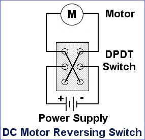
So if red and white have power, they should swap sides between the top and bottom and your motor will connect to the center 2 pins.
So if red and white have power, they should swap sides between the top and bottom and your motor will connect to the center 2 pins.
Options
- Mark as New
- Bookmark
- Subscribe
- Mute
- Subscribe to RSS Feed
- Permalink
- Report Inappropriate Content
Apr-01-2017 09:13 PM
I plan on taking some more voltage values and then pulling the fuse for the slide. Then pull the wires off the the back of the switch and check for continuity (resistance) between all the possibilities I can come up with. As I have already mentioned, with the slide switch in the neutral position there is no resistance between the blue and green wires. Be interesting to see what happens when the fuse is pulled and the switch toggled to in and out positions. Seems like what I have to do is getting in the way of what I want to do, so maybe tomorrow after church I will be able to get this done. I do remember though, while I was checking voltages the probes caused a momentary retraction of the slide to occur. Seems like that happened while I was checking the lower red and white leads and may have been touching the green or blue wire while probing the red lead. Sure be a lot safer to have the fuse pulled.
Options
- Mark as New
- Bookmark
- Subscribe
- Mute
- Subscribe to RSS Feed
- Permalink
- Report Inappropriate Content
Apr-01-2017 05:55 AM
Bigbird: I'm just guessing, but this is how I think the switch works. The red and white wires on back of switch are hot and ground. The green and blue center wires go to the motor - one goes to the motor and one comes back from motor to switch. In one switch position, the red hot wire is connected to the blue wire to the motor and the white (ground) wire is connected to the green wire from the motor. In the other switch position, the connections are reversed - red to green and white to blue. This causes the motor to rotate in one direction in one switch position and the opposite direction in the other switch position. If I'm correct, don't jumper the red to white - you'll be shorting your battery terminals and create a lot of sparks!
Ken
Ken
2007 FORD F-350 4WD SC Longbed, 6.0L Powerstroke
2018 Rockwood 2706WS
2018 Rockwood 2706WS
Options
- Mark as New
- Bookmark
- Subscribe
- Mute
- Subscribe to RSS Feed
- Permalink
- Report Inappropriate Content
Apr-01-2017 05:51 AM
For safety reasons, it is unlikely that any power would go direct to the motor... if for any reason while travelling, a ground showed up somewhere (water or otherwise), deployment of a slide wouldn't be nice.
Anyways, I hope your investigation helps determine where things might be going wrong during travel. The switch configuration is very similar to how "most" dc control switching is done. ie. two wire switching. I would look very closely at the mechanics / internals of the switch.
Anyways, I hope your investigation helps determine where things might be going wrong during travel. The switch configuration is very similar to how "most" dc control switching is done. ie. two wire switching. I would look very closely at the mechanics / internals of the switch.
Options
- Mark as New
- Bookmark
- Subscribe
- Mute
- Subscribe to RSS Feed
- Permalink
- Report Inappropriate Content
Mar-31-2017 08:09 PM
What I know, I think, is that there is one hot + red wire coming into the switch and that it is split just before the switch to the two reds on the back of the switch. I could jumper between the red and white leads to see if it activated the slide motor and if the top two control the retract and the bottom two control the extend function. I can also check the green and blue wire for voltage against the white wires (which have ground potential), they show very little difference from the red + wires. What the described set up says to me is that the hot lead does not go directly to the slide motor, but instead to the rocker switch. I will do some more testing to see if I can prove it. If the hot went direct to the motor then there would be two separate hot wires to the rocker switch that would go to ground to complete the circuit. I know of no way that one hot from the motor could activate in and out slide function. But I have been wrong before and hate it. Again, a complete schematic would be nice.
Options
- Mark as New
- Bookmark
- Subscribe
- Mute
- Subscribe to RSS Feed
- Permalink
- Report Inappropriate Content
Mar-31-2017 05:43 PM
Although you did a lot of good testing, I think you still had "one assume" which is usually bad. Further the "assume" is potentially wrong, literally and figuratively... 🙂 It is more likely that the blue and green are not connected to anything at least during your "voltage check" which means your .002v is just "air leakage".... like holding your probes in mid air. Just a guess.
As suggested in general, measurements need to be reference back to a KNOWN ground... this is true for both voltage and resistance.
I suspect you might find that the red and blue are open at "neutral setting".
Not sure of the type of switch and how the wiring is down, but if you can disconnect it from the wires easily and take some resistance measure to check which contact make which contact during "neutral-nothing, in, and out" you should be able to deduce more about what you are up against... hopefully.
My guess is that the green and blue go to the motor (very low resistance as in almost 0). When you move the switch one way, one set of voltages are made from one side. When you go the other way, some how those are reversed.
PS... oops corrected the colors
final oops, yes, agree that the red path to switch from the fuse is the one in "question".... assuming nothing is rattling around in the switch itself.


