Turn on suggestions
Auto-suggest helps you quickly narrow down your search results by suggesting possible matches as you type.
Showing results for
- Good Sam Community
- Everything RV
- RV Tips & Tricks
- 3500lb axles bad design
Options
- Subscribe to RSS Feed
- Mark Topic as New
- Mark Topic as Read
- Float this Topic for Current User
- Bookmark
- Subscribe
- Mute
- Printer Friendly Page
3500lb axles bad design
Options
- Mark as New
- Bookmark
- Subscribe
- Mute
- Subscribe to RSS Feed
- Permalink
- Report Inappropriate Content
Feb-20-2018 03:56 PM
Probably most medium size trailers have the 3500lb axles and 10" brakes. The design of the spindles has little to no shoulder to locate the inner bearing. When I looked up the blueprints, I found that the spindle shoulder has a contact area against the ground surface of the bearing of about .020" and can be as little as zero using the print tolerances. That extremely small contact area can cause burrs, seal damage, loss of bearing adjustment and bearing alignment.
Today, I pulled and serviced all four hubs and found contaminated grease in two of them. The metal wearing away from the spindle contact area was the issue. The ground surface of a bearing is where it is to take the load, not the roughed in clearance radius.
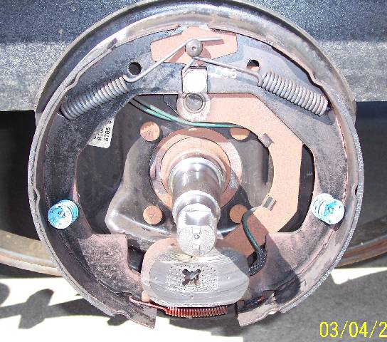
To show you what I am talking about, in this photo is the blackened grease and a narrow band of metal which is the contact area that takes the lateral load of the trailer.

Here is a photo showing the result of the bearing radius carving its way into the spindle shoulder.

This photo shows the bearing with bluing so that the contact area can be found. Of course the bearing is on the spindle backwards for its photo op. The narrow dark blue band is the only support designed into this spindle. The lighter blue areas are where the roughed in radius is now locating the bearing.

I do not have an easy fix for this design fault. Short of replacing the axles with 5200lb units, all we can do is frequent bearing cleaning and repacking. For those that choose to use the grease fittings, just remember that the metal shards will be pushed to the outer bearing and the bearing adjustment still needs to be done frequently.
Here is a view of the metal shards I am talking about:

Today, I pulled and serviced all four hubs and found contaminated grease in two of them. The metal wearing away from the spindle contact area was the issue. The ground surface of a bearing is where it is to take the load, not the roughed in clearance radius.
To show you what I am talking about, in this photo is the blackened grease and a narrow band of metal which is the contact area that takes the lateral load of the trailer.
Here is a photo showing the result of the bearing radius carving its way into the spindle shoulder.
This photo shows the bearing with bluing so that the contact area can be found. Of course the bearing is on the spindle backwards for its photo op. The narrow dark blue band is the only support designed into this spindle. The lighter blue areas are where the roughed in radius is now locating the bearing.
I do not have an easy fix for this design fault. Short of replacing the axles with 5200lb units, all we can do is frequent bearing cleaning and repacking. For those that choose to use the grease fittings, just remember that the metal shards will be pushed to the outer bearing and the bearing adjustment still needs to be done frequently.
Here is a view of the metal shards I am talking about:
35 REPLIES 35
Options
- Mark as New
- Bookmark
- Subscribe
- Mute
- Subscribe to RSS Feed
- Permalink
- Report Inappropriate Content
Feb-23-2018 04:06 PM
I looked at the information you found, that .130" less shoulder contact is huge when you consider that the #84 spindle has next to nothing. My thought is that nearly all trailer axles have about the same bearing to spindle clearance as I have found.
The idea just mentioned about using an adhesive would work, I even have plenty of the right type on hand. The problem is that the spindle would become very difficult to service and might require heat to disassemble. With PA state inspections pulling the hubs yearly, that is not an option.
The idea just mentioned about using an adhesive would work, I even have plenty of the right type on hand. The problem is that the spindle would become very difficult to service and might require heat to disassemble. With PA state inspections pulling the hubs yearly, that is not an option.
Options
- Mark as New
- Bookmark
- Subscribe
- Mute
- Subscribe to RSS Feed
- Permalink
- Report Inappropriate Content
Feb-23-2018 01:55 PM
I didn't read all four pages of this but if you are have a problem with the race spinning due a gap of just a couple thou, wouldn't this be a good application for loctite bearing mount ?
Here is a link to the specs for it:
http://na.henkel-adhesives.com/us/content_data/316041_FINAL_LT4680_AAM_Do_It_Guide_v7.pdf
Here is a link to the specs for it:
http://na.henkel-adhesives.com/us/content_data/316041_FINAL_LT4680_AAM_Do_It_Guide_v7.pdf
Options
- Mark as New
- Bookmark
- Subscribe
- Mute
- Subscribe to RSS Feed
- Permalink
- Report Inappropriate Content
Feb-23-2018 11:40 AM
I’m on the cell phone right now, I’ll review your resources better when I get to the computer. To answers some questions, I emailed Dexter in hopes of getting answers in writing, but no response so far. The bearings were new Timken with about 6,000 miles on them. I did notice that the Timken is cut away even farther than other bearings I checked. I should have taken a photo of the Al-Ko axle showing that there is only contact with the sharp corner of the bearing with the radius on the spindle. Unbelievable!
I still think that the loss of bearing adjustment caused by the shoulder issue, causes bearing races to lose the proper relationship with each other. That small shoulder will wear or deform at an angle due to the way weight and side loads act on it. In addition, the unground radius and relief is not necessarily running true and it becomes the support surface. With races and rollers skewed with the spindle centerline, some torque is applied and causes the spin. Now that is my opinion, I do like to use facts.
One curious thing is that both bearings spun on the left side and no sing of spinning on the right.
Options
- Mark as New
- Bookmark
- Subscribe
- Mute
- Subscribe to RSS Feed
- Permalink
- Report Inappropriate Content
Feb-23-2018 09:28 AM
Lynnmor wrote:JBarca wrote:
I found this, this tells us having a resultant clearance of 0.0019" between the bearing bore and the spindle OD is out of tolerance by 0.0007" too big.
Your bearing would fall in the 0" to 3" bore bearing chart on page 2
https://www.timken.com/pdf/10829_MDV5-Correct-Fits-For-Your-Wheel-Bearing.pdf
As I thought, the ideal middle of the clearance resultant fit spec is 0.0007" clear between spindle and bearing. They declare a min of 0.0002" clear to 0.0012" max between the shaft and the bearing. See page 2, under bearing cone bore diameter.
It looks like you to much running clearance between the shaft and the bearing bore.
Hope this helps.
John
Thanks for that. I really wanted to find the manufacturing tolerances for the bearing and spindle. We both know that a perfect fit would be best. I did find that the bearing is to be 1.3775" to 1.3780" The spindle size is to be 1.3760" and that is what I have so with unknown tolerances, the clearance could be greater.
So anyway, at .0019" my parts are within the specification of .0015" to .0020", so again that clearance could be even greater if we had the spindle tolerance.
I have another bare axle of a different brand that I will measure tomorrow.
Hi Lynnmor,
This has me bugged now and is a good post to figure out why that bearing spun.
We both are coming up close on the bearing. I tried to find the bearing on the Timken site but that site is so big that trying to find what I want, is always a challenge. I'm an older handbook guy...
So I went to the SKF site where I have more luck most times. I have a set of new SKF L68149/L68111 bearings in my shop now left over from years ago when I had the smaller camper. But my mic's stop at 1". Work always had the bigger stuff.
Here is the bearing, SKF L 68149/111 Tapered roller dim's
And here is the tolerances. You start at this page SKF Tolerance list page
And this puts you into Taper Roller tolerances. SKF Tapered Roller Tolerance You are looking for the t delt tmv
This comes out to a bore of 1.3774" + 0.0005" /- 0.0000"
So what you found is within a tenth, so OK we are good on that.
And if your bearing that you measured is 1.3779" it is sitting on the top edge of the bearing tolerance. By any chance, was that the bearing that scored the shoulder or a new one in a box?
They declare the shaft shoulder to be 1.8504" min. See here, scroll down a little and look for d sub b SKF shaft shoulder recommendations
That 1.8504" min SKF recommendation shoulder seems to conflict "I think" with what spindle is. While the spindle is smaller, I'm still not seeing that the reason to cause the bearing to spin.
So far I cannot find the spindle tolerance. Have you tried calling Dexter what is it they use?
Here are my current thoughts on this. On the bearing and spindle you measured (don't know if that is the scored spindle/bearing) there is 0.0019" clearance.
That's a lot of clearance in my view. If I was spec'ing out a running fit for a shaft and a bronze bushing in a medium duty application, using a rule of thumb of 0.001"/ 1 inch of diameter, on a 1.3750/1.3745 shaft, I would set the bushing bore at 1.3763/1.3768. This will give me a running clearance of 0.0013/0.0023" and the shaft will spin all day/week/year long as long as it has lube and run at normal temps.
If you have a 0.0019" clearance on your bearing to spindle, how is that ever going to lock up enough to hold the bearing race from spinning?
A fundamental unknown in this, what is the max clearance between shaft and bearing to allow the bearing to tip and lock up on the shaft under load so it is easier to spin the bearing on the rollers then the bore?
If you go by the Timken specs I listed above, this appears they do not want any more clearance then 0.0012" max.
We really need a spec on the spindle to help solve this.
I'm curious as all get out right now on how this is supposed to work by the numbers.
Hope this helps
John
2005 Ford F350 Super Duty, 4x4; 6.8L V10 with 4.10 RA, 21,000 GCWR, 11,000 GVWR, upgraded 2 1/2" Towbeast Receiver. Hitched with a 1,700# Reese HP WD, HP Dual Cam to a 2004 Sunline Solaris T310R travel trailer.
Options
- Mark as New
- Bookmark
- Subscribe
- Mute
- Subscribe to RSS Feed
- Permalink
- Report Inappropriate Content
Feb-23-2018 05:54 AM
I checked the Al-Ko axle and found that one end measured 1.3764" and the other end was 1.3749". The radius where the bearing contacts was large enough to completely eliminate a square shoulder contact surface. I suspect that all dimensions that I checked on two brands of bearings and two brands of axles were within the design tolerances, but without the axle blueprints it can only be a guess. Regardless, it is a bad design any way you look at it.
Options
- Mark as New
- Bookmark
- Subscribe
- Mute
- Subscribe to RSS Feed
- Permalink
- Report Inappropriate Content
Feb-22-2018 05:08 PM
JBarca wrote:
I found this, this tells us having a resultant clearance of 0.0019" between the bearing bore and the spindle OD is out of tolerance by 0.0007" too big.
Your bearing would fall in the 0" to 3" bore bearing chart on page 2
https://www.timken.com/pdf/10829_MDV5-Correct-Fits-For-Your-Wheel-Bearing.pdf
As I thought, the ideal middle of the clearance resultant fit spec is 0.0007" clear between spindle and bearing. They declare a min of 0.0002" clear to 0.0012" max between the shaft and the bearing. See page 2, under bearing cone bore diameter.
It looks like you to much running clearance between the shaft and the bearing bore.
Hope this helps.
John
Thanks for that. I really wanted to find the manufacturing tolerances for the bearing and spindle. We both know that a perfect fit would be best. I did find that the bearing is to be 1.3775" to 1.3780" The spindle size is to be 1.3760" and that is what I have so with unknown tolerances, the clearance could be greater.
So anyway, at .0019" my parts are within the specification of .0015" to .0020", so again that clearance could be even greater if we had the spindle tolerance.
I have another bare axle of a different brand that I will measure tomorrow.
Options
- Mark as New
- Bookmark
- Subscribe
- Mute
- Subscribe to RSS Feed
- Permalink
- Report Inappropriate Content
Feb-22-2018 03:22 PM
I found this, this tells us having a resultant clearance of 0.0019" between the bearing bore and the spindle OD is out of tolerance by 0.0007" too big.
Your bearing would fall in the 0" to 3" bore bearing chart on page 2
https://www.timken.com/pdf/10829_MDV5-Correct-Fits-For-Your-Wheel-Bearing.pdf
As I thought, the ideal middle of the clearance resultant fit spec is 0.0007" clear between spindle and bearing. They declare a min of 0.0002" clear to 0.0012" max between the shaft and the bearing. See page 2, under bearing cone bore diameter.
It looks like you to much running clearance between the shaft and the bearing bore.
Hope this helps.
John
2005 Ford F350 Super Duty, 4x4; 6.8L V10 with 4.10 RA, 21,000 GCWR, 11,000 GVWR, upgraded 2 1/2" Towbeast Receiver. Hitched with a 1,700# Reese HP WD, HP Dual Cam to a 2004 Sunline Solaris T310R travel trailer.
Options
- Mark as New
- Bookmark
- Subscribe
- Mute
- Subscribe to RSS Feed
- Permalink
- Report Inappropriate Content
Feb-22-2018 02:27 PM
Lynnmor wrote:
I pulled that hub and measured.
Spindle is 1.3760" should be 1.3760"
Bearing is 1.3779" should be 1.3775"
(A Chinese bearing measured exactly the same.)
Nominal clearance is .0015"
Mine is .0019"
I couldn't readily find a source of tolerances, but I would think a deviation from nominal of .0004" would be acceptable.
Hi,
This is good info. On bearing fits, 0.0005" can be the difference in working or not. Need to drill into what the min and max running clearance needs to be to work properly. I normally deal with interference fits on bearings, so what I have out of my head will not apply here. Have to do some digging into the max clearance and when you exceed that, the bearing will spin. 0.0019" clear sounds "big" to me.
The bearing will slide on with 0.0005" to 0.001" clearance. Having a lot more than that my gut says it's not good. Need to dig in on this and report back.
Thanks
John
2005 Ford F350 Super Duty, 4x4; 6.8L V10 with 4.10 RA, 21,000 GCWR, 11,000 GVWR, upgraded 2 1/2" Towbeast Receiver. Hitched with a 1,700# Reese HP WD, HP Dual Cam to a 2004 Sunline Solaris T310R travel trailer.
Options
- Mark as New
- Bookmark
- Subscribe
- Mute
- Subscribe to RSS Feed
- Permalink
- Report Inappropriate Content
Feb-22-2018 10:17 AM
I pulled that hub and measured.
Spindle is 1.3760" should be 1.3760"
Bearing is 1.3779" should be 1.3775"
(A Chinese bearing measured exactly the same.)
Nominal clearance is .0015"
Mine is .0019"
I couldn't readily find a source of tolerances, but I would think a deviation from nominal of .0004" would be acceptable.
Spindle is 1.3760" should be 1.3760"
Bearing is 1.3779" should be 1.3775"
(A Chinese bearing measured exactly the same.)
Nominal clearance is .0015"
Mine is .0019"
I couldn't readily find a source of tolerances, but I would think a deviation from nominal of .0004" would be acceptable.
Options
- Mark as New
- Bookmark
- Subscribe
- Mute
- Subscribe to RSS Feed
- Permalink
- Report Inappropriate Content
Feb-22-2018 09:09 AM
JBarca wrote:
The bearing bore, it is dead on center tolerance within 4 decimal places or is it sitting on the large end of the tolerance?
The shaft OD, it is dead on center tolerance within 4 decimal places or is it sitting on the small end of the tolerance?
You will need a mic to get that close, a caliper has more chances of error in it which I'm sure you know.
That would be my first place to look. It would not shock me in the least the shaft is ground small or the bearing race too big. Once the bearing starts spinning on the shaft under load, its all over and it's going to gall something. Yes, this is not an interference fit as it has to slide on, but the fit has to be right or the bearing will spin.
Again I agree the shaft shoulder is small, but that small shoulder is not changing the friction holding the bearing from spinning.
Thanks for the reply.
While I did not actually measure the parts, I did manually check the fit when dry and noticed no excess play. Yes, I should have measured and I do have a tool& die shop, so I could have obtained very accurate readings. Maybe I'll pull the worst one and get some measurements.
The bearing obviously did spin to form the burrs and the jury is still out as to what caused the spin. My first thought was that the shoulder giving way and causing excess bearing end play was a factor. With poor mating of the rollers to the race, caused by that excess play, might increase the torque and was the reason for the spin.
Options
- Mark as New
- Bookmark
- Subscribe
- Mute
- Subscribe to RSS Feed
- Permalink
- Report Inappropriate Content
Feb-22-2018 08:44 AM
time2roll wrote:
I would put the question directly to Dexter. No way could all 3500 axles be defective for decades on end.
I did ask Dexter at the same time as my original post, still awaiting answers.
It is the way they have been made for decades, I simply pointed out what I found. If you have other information, please share.
Options
- Mark as New
- Bookmark
- Subscribe
- Mute
- Subscribe to RSS Feed
- Permalink
- Report Inappropriate Content
Feb-22-2018 08:40 AM
Hi Lynnmor
I'm not arguing the fact of a small contact shoulder, its small. I'm just trying to help as I see something that is not right with the parts beyond the small shoulder.
As you described the bearing inner race is eating into the spindle. While a larger shaft shoulder will lower the psi contact pressure of the thrust load, a larger shoulder will not change the friction between the bearing race and the spindle shoulder. Bear with me a moment and think through what I am going to say/show.
Here is your spindle. We can see the galling going on. The shaft shoulder is galled and where the slivers are coming from.
I went and looked at all my pics when I had my smaller camper and I found this one. 3500# Dexter axles. I found these 2.
The assembly with the drum off and cleaned up. Nothing special on this one, just showing it.
Now a zoom in on the shoulder.

The zoom in shows no galling on the thrust shoulder. That is a key difference.
On yours, in order to gall steel in the pattern you have this points to the bearing race rotating. If you use a 10X loop or other magnifier you can see the score lines. They should be radial. If they are radial, the bearing was spinning. If the score lines are not radial, more jagged all over the place, then this points to maybe an impact loading smash which I'm not really thinking that's the case, it's more a radial gall.
That galling is the problem and I think you see that as I do. So the question is, where is the gall coming from?
The laws of friction do not have surface area in the equation at all. Force and the surface material coefficient of friction are the 2 variables that have to change. Not surface area.
Once that thought is realized, how did the gall happen?
The bearing bore, it is dead on center tolerance within 4 decimal places or is it sitting on the large end of the tolerance?
The shaft OD, it is dead on center tolerance within 4 decimal places or is it sitting on the small end of the tolerance?
You will need a mic to get that close, a caliper has more chances of error in it which I'm sure you know.
That would be my first place to look. It would not shock me in the least the shaft is ground small or the bearing race too big. Once the bearing starts spinning on the shaft under load, its all over and it's going to gall something. Yes, this is not an interference fit as it has to slide on, but the fit has to be right or the bearing will spin.
The other part of the equation is the coefficient of friction of the 2 steels changed. That is a lot harder to check. Hardness could be off or the steel itself. I would put this steel factor lower in odds of the issue, odds are much higher there is a bearing fit issue.
Again I agree the shaft shoulder is small, but that small shoulder is not changing the friction holding the bearing from spinning.
Hope this helps
John
I'm not arguing the fact of a small contact shoulder, its small. I'm just trying to help as I see something that is not right with the parts beyond the small shoulder.
As you described the bearing inner race is eating into the spindle. While a larger shaft shoulder will lower the psi contact pressure of the thrust load, a larger shoulder will not change the friction between the bearing race and the spindle shoulder. Bear with me a moment and think through what I am going to say/show.
Here is your spindle. We can see the galling going on. The shaft shoulder is galled and where the slivers are coming from.
I went and looked at all my pics when I had my smaller camper and I found this one. 3500# Dexter axles. I found these 2.
The assembly with the drum off and cleaned up. Nothing special on this one, just showing it.
Now a zoom in on the shoulder.
The zoom in shows no galling on the thrust shoulder. That is a key difference.
On yours, in order to gall steel in the pattern you have this points to the bearing race rotating. If you use a 10X loop or other magnifier you can see the score lines. They should be radial. If they are radial, the bearing was spinning. If the score lines are not radial, more jagged all over the place, then this points to maybe an impact loading smash which I'm not really thinking that's the case, it's more a radial gall.
That galling is the problem and I think you see that as I do. So the question is, where is the gall coming from?
The laws of friction do not have surface area in the equation at all. Force and the surface material coefficient of friction are the 2 variables that have to change. Not surface area.
Once that thought is realized, how did the gall happen?
The bearing bore, it is dead on center tolerance within 4 decimal places or is it sitting on the large end of the tolerance?
The shaft OD, it is dead on center tolerance within 4 decimal places or is it sitting on the small end of the tolerance?
You will need a mic to get that close, a caliper has more chances of error in it which I'm sure you know.
That would be my first place to look. It would not shock me in the least the shaft is ground small or the bearing race too big. Once the bearing starts spinning on the shaft under load, its all over and it's going to gall something. Yes, this is not an interference fit as it has to slide on, but the fit has to be right or the bearing will spin.
The other part of the equation is the coefficient of friction of the 2 steels changed. That is a lot harder to check. Hardness could be off or the steel itself. I would put this steel factor lower in odds of the issue, odds are much higher there is a bearing fit issue.
Again I agree the shaft shoulder is small, but that small shoulder is not changing the friction holding the bearing from spinning.
Hope this helps
John
2005 Ford F350 Super Duty, 4x4; 6.8L V10 with 4.10 RA, 21,000 GCWR, 11,000 GVWR, upgraded 2 1/2" Towbeast Receiver. Hitched with a 1,700# Reese HP WD, HP Dual Cam to a 2004 Sunline Solaris T310R travel trailer.
Options
- Mark as New
- Bookmark
- Subscribe
- Mute
- Subscribe to RSS Feed
- Permalink
- Report Inappropriate Content
Feb-22-2018 07:09 AM
I would put the question directly to Dexter. No way could all 3500 axles be defective for decades on end.
Options
- Mark as New
- Bookmark
- Subscribe
- Mute
- Subscribe to RSS Feed
- Permalink
- Report Inappropriate Content
Feb-21-2018 05:46 PM
wilber1 wrote:
What make of axle? Lippert axles have been notorious for grease covered brakes. 215 so far on the Grand Design forum alone. Word is they have switched to Dexter.
They are Dexter, but that doesn't matter. A #84 spindle is the same dimensions and bearings regardless of brand. I understand that Lippert may have used inferior seals at one time, but I have no proof of that.


