- Good Sam Community
- Everything RV
- DIY Maintenance
- Cheap ammeter for power hungry RV's
- Subscribe to RSS Feed
- Mark Topic as New
- Mark Topic as Read
- Float this Topic for Current User
- Bookmark
- Subscribe
- Mute
- Printer Friendly Page
Cheap ammeter for power hungry RV's
- Mark as New
- Bookmark
- Subscribe
- Mute
- Subscribe to RSS Feed
- Permalink
- Report Inappropriate Content
Jul-01-2016 06:53 AM
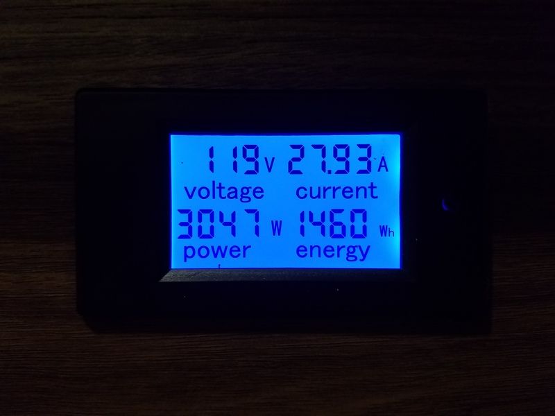
This 5er is 42' long, and comes factory equipped for 50amp service. We know that we will end up in a few 30amp campground spots, so being able to quickly determine our power consumption is important. There are are a number of RV specific meters out there that range from $80-$300 dollars and provide all sorts of data, but I know what I needed: voltage supplied, amps drawn, overall watts being used and energy consumption (KWh). With that in mind, I set out to find a panel mount ammeter that isn't difficult to install, yet provides accurate information. So why an electrical project as my first DIY? probably because I'm an electronic nerd. Love the stuff! I've been around high A/C voltage for my entire adult life and have a HEALTHY respect for what it is capable of doing. If you're not totally comfortable working with A/C power circuits this mod may not be for you.
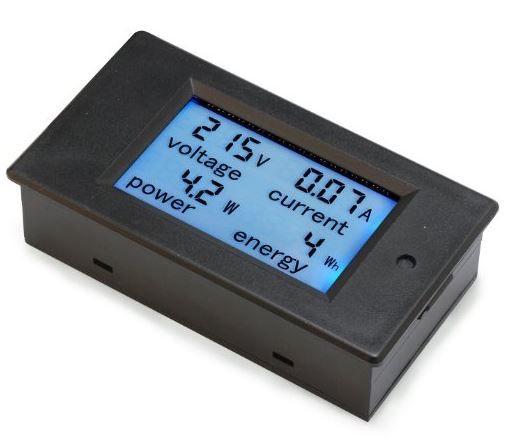
After some quick searching, I ended up with this little doo-dad from a company called droking.com

It can be bought here: Digital Meter unit
They make a number of units, so make sure you pick the one that fits your power consumption parameters. I needed to check 120 volts, up to 50 amps per leg so the one above is what I picked.
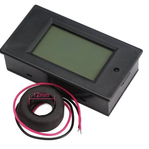
This little device is super simple to install. there are 4 lugs on the back of the unit where wires connect. Two of them are for A/C power two of them go to the Center Tapped transformer ring that measures apparent power. This ring is the key to how this works. By using a CT transformer, the unit picks up apparent power being used via magnetic field. The windings in the sealed ring put out power at a compensated level that can then be measured by the device to provide usage information.
The down side to this device is that it is only capable of measuring one side of the 50A service being supplied to the 5er. The upside is that they're cheap enough you can order two and have independent measurement of each side of the 50A service.
Those running 30A service would be perfectly happy with just a single meter. four wires from the inside of the breaker panel to this device is all it takes to install. The CT transformer does require disconnecting the main power cable from the breaker panel. once the ring is slipped onto the wire, the cable can be reconnected. Note: there is no cutting, or interrupting the main power cable. all you have to do is disconnect the cable, slip the ring on, reconnect the cable. If this unit ever quits working, it cannot disrupt power.
Here's what the CT transformer ring looks like:

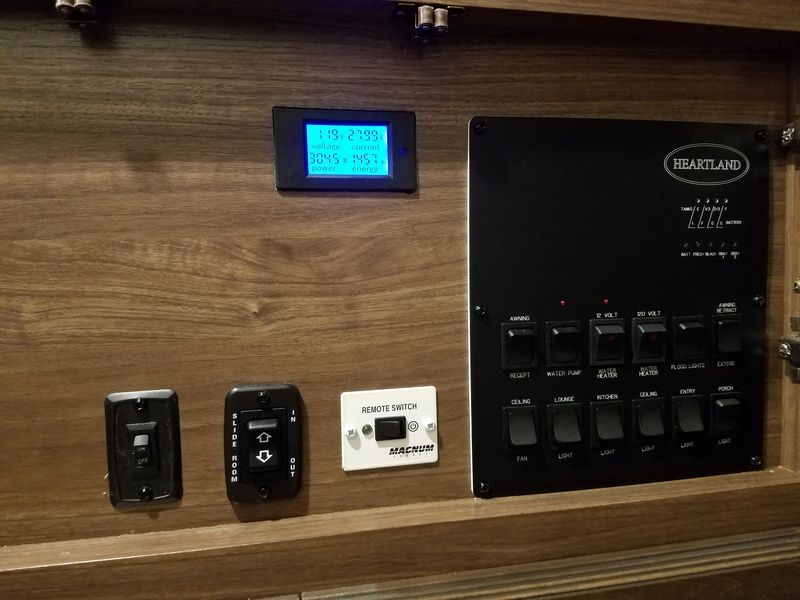
Here's the finished install. Turned out pretty good.


The DC version uses a shunt to glean information, but it would be a great alternative for a solar setup to see how much power is being generated by the solar system.
you could also use the AC version to monitor total power load on an inverter, or coming from a generator... Lots of uses - for $17 how can you go wrong?
- Mark as New
- Bookmark
- Subscribe
- Mute
- Subscribe to RSS Feed
- Permalink
- Report Inappropriate Content
Jul-05-2016 08:48 AM
DrewE wrote:tarnold wrote:
Could you be more specific about what wires go where? Looking at the back of the unit, the wire taps from top to bottom. Understand no printed instructions, just diagram on back of unit. Also is there a problem with lengthen those short supplied leads?
I guess I don't see what's so confusing about the diagram. Two of the wires go to the current transformer (the dounut thingy), which has the wire you want the current measured passed through the center. The other two go to the hot and neutral lines to measure the voltage and power the meter. I don't think it cares about polarity one way or the other...if it does, swapping the two wires in either the current sense or the voltage sense pair will take care of things.
In most cases it would be necessary or at least advisable to lengthen the wires by splicing on some additional wire. I used "security alarm wire" which is 120V rated multiconductor cabling in fairly small gauges. I put in (and recommend) a smallish (1A) AC fuse at the hot connection since the wire is a good bit smaller than the 12 gauge wire of the circuit I used.
(The voltage sense line ought to be from a branch circuit, IMHO, and not tapped into the main line coming into the RV. If for no other reason, this ensures that the main breakers in the RV panel will turn off AC power to everything in the RV, including the meter. I put the voltage sense connection on my air conditioner circuit since I decided that's the one I care about the voltage on the most...though close to the electric panel it really doesn't matter much since there should be no significant voltage drop on any of the circuits.)
My setup is very similar. I used 6 pair 600v rated wire to run my panel. The maker recommends using twisted pair stranded cable and that makes sense.
My extension cable was, I think, about 8 feet long.
- Mark as New
- Bookmark
- Subscribe
- Mute
- Subscribe to RSS Feed
- Permalink
- Report Inappropriate Content
Jul-05-2016 08:28 AM
tarnold wrote:
Could you be more specific about what wires go where? Looking at the back of the unit, the wire taps from top to bottom. Understand no printed instructions, just diagram on back of unit. Also is there a problem with lengthen those short supplied leads?
I guess I don't see what's so confusing about the diagram. Two of the wires go to the current transformer (the dounut thingy), which has the wire you want the current measured passed through the center. The other two go to the hot and neutral lines to measure the voltage and power the meter. I don't think it cares about polarity one way or the other...if it does, swapping the two wires in either the current sense or the voltage sense pair will take care of things.
In most cases it would be necessary or at least advisable to lengthen the wires by splicing on some additional wire. I used "security alarm wire" which is 120V rated multiconductor cabling in fairly small gauges. I put in (and recommend) a smallish (1A) AC fuse at the hot connection since the wire is a good bit smaller than the 12 gauge wire of the circuit I used.
(The voltage sense line ought to be from a branch circuit, IMHO, and not tapped into the main line coming into the RV. If for no other reason, this ensures that the main breakers in the RV panel will turn off AC power to everything in the RV, including the meter. I put the voltage sense connection on my air conditioner circuit since I decided that's the one I care about the voltage on the most...though close to the electric panel it really doesn't matter much since there should be no significant voltage drop on any of the circuits.)
- Mark as New
- Bookmark
- Subscribe
- Mute
- Subscribe to RSS Feed
- Permalink
- Report Inappropriate Content
Jul-05-2016 06:21 AM
- Mark as New
- Bookmark
- Subscribe
- Mute
- Subscribe to RSS Feed
- Permalink
- Report Inappropriate Content
Jul-04-2016 09:51 PM
We were able to tweak what was running and creep right up to the 30A mark - all while running both AC's all weekend....all three days. we kept the water heater on propane, and shut off the back AC to run the microwave one time. Other than that, the fridge was fine all weekend as were all the electronics we were all charging PLUS we set up a brand new PathwayX2 on new service. works great.
I have my second unit in my hand this evening and will have it installed before the week is out. I am totally sold on these little ammeters. Information is golden.
- Mark as New
- Bookmark
- Subscribe
- Mute
- Subscribe to RSS Feed
- Permalink
- Report Inappropriate Content
Jul-01-2016 02:25 PM
Chuck_thehammer wrote:aviator41 wrote:Chuck_thehammer wrote:
so the high dollar protector is protecting the power inverter and Air Conditioner.. maybe a television or 2. an/or a residential refrigerator
every thing else is powered by 12 volts correct?
I have every dollar I have in my used truck and trailer for snowbirding... this coming will be year number 2.
I have an analog 120 volt meter hooked up full time.. and a digital 12 volt meter next to it.
my wood home.. in 40 years.. we lost the common of the 220 volt circuit once... No damage... but my Ham radio tower has been hit by lightning 17 times... no damage as its protected per National weather service information. except for the fuse .. that is how I know it was hit by lightning.
I hope you never need the high dollar protection.
it would be nice if REAL information and real numbers of
trailers damaged and destroyed by bad power to trailer/motorhomes..
and not what is just talked about.
Sorry for the derailment...
if I can earn a little extra doing yard work this summer .. I like the 20 dollar 30 amp unit..
Thank You for the nice write-up.. on an affordable meter.
It's interesting you mention your ham tower. I, too am a ham. Our tower here in Oklahoma gets a strike once a year on average. Sometimes more. It's quite the loud crack and we KNOW when it happens but like you, we installed our tower in accordance with NWS recommendations and have never lost of piece of equipment to lightning, just a fuse blown.
I have only been home once when lightning hit the tower... LOUD is an under statement. I live in a small valley and have many trees much higher that my 60 foot tower. and a 2 meter dipole above that...
Our QTH is among some rolling hills. while the tower doesn't reach above the trees, the antenna does. It' just a little dual band omni right now.
You got the loud comment right! I would SWEAR the first time the antenna got hit, it cracked a back window in our house. The DW still thinks it was just a coincidence.
- Mark as New
- Bookmark
- Subscribe
- Mute
- Subscribe to RSS Feed
- Permalink
- Report Inappropriate Content
Jul-01-2016 01:49 PM
aviator41 wrote:Chuck_thehammer wrote:
so the high dollar protector is protecting the power inverter and Air Conditioner.. maybe a television or 2. an/or a residential refrigerator
every thing else is powered by 12 volts correct?
I have every dollar I have in my used truck and trailer for snowbirding... this coming will be year number 2.
I have an analog 120 volt meter hooked up full time.. and a digital 12 volt meter next to it.
my wood home.. in 40 years.. we lost the common of the 220 volt circuit once... No damage... but my Ham radio tower has been hit by lightning 17 times... no damage as its protected per National weather service information. except for the fuse .. that is how I know it was hit by lightning.
I hope you never need the high dollar protection.
it would be nice if REAL information and real numbers of
trailers damaged and destroyed by bad power to trailer/motorhomes..
and not what is just talked about.
Sorry for the derailment...
if I can earn a little extra doing yard work this summer .. I like the 20 dollar 30 amp unit..
Thank You for the nice write-up.. on an affordable meter.
It's interesting you mention your ham tower. I, too am a ham. Our tower here in Oklahoma gets a strike once a year on average. Sometimes more. It's quite the loud crack and we KNOW when it happens but like you, we installed our tower in accordance with NWS recommendations and have never lost of piece of equipment to lightning, just a fuse blown.
I have only been home once when lightning hit the tower... LOUD is an under statement. I live in a small valley and have many trees much higher that my 60 foot tower. and a 2 meter dipole above that...
- Mark as New
- Bookmark
- Subscribe
- Mute
- Subscribe to RSS Feed
- Permalink
- Report Inappropriate Content
Jul-01-2016 01:28 PM
2oldman wrote:Chuck_thehammer wrote:Inverters are usually powered by 12v
so the high dollar protector is protecting the power inverter and Air Conditioner.. maybe a television or 2. an/or a residential refrigerator every thing else is powered by 12 volts correct?ter.
Thank You,,, I did miss one.
I have a Harbor Fright 400 watt inverter in my trailer .. to runs the 32 inch TV and satellite receiver.. when there is NO electric.
- Mark as New
- Bookmark
- Subscribe
- Mute
- Subscribe to RSS Feed
- Permalink
- Report Inappropriate Content
Jul-01-2016 01:23 PM
BarneyS wrote:
I did, and edited his post to make the cookie the same size as yours. :B
Barney
Thank you BarneyS. I guess bigger isn't always better. :B 😉
- Mark as New
- Bookmark
- Subscribe
- Mute
- Subscribe to RSS Feed
- Permalink
- Report Inappropriate Content
Jul-01-2016 01:00 PM
2oldman wrote:pianotuna wrote:Maybe he'll notice my post.
(can you change the size of the cookie please--scrolling side to side is not much fun!)
I did, and edited his post to make the cookie the same size as yours. :B
Barney
Hensley "Arrow" 1400# hitch (Sold)
Not towing now.
Former tow vehicles were 2016 Ram 2500 CTD, 2002 Ford F250, 7.3 PSD, 1997 Ram 2500 5.9 gas engine
- Mark as New
- Bookmark
- Subscribe
- Mute
- Subscribe to RSS Feed
- Permalink
- Report Inappropriate Content
Jul-01-2016 12:28 PM
pianotuna wrote:Maybe he'll notice my post.
(can you change the size of the cookie please--scrolling side to side is not much fun!)
- Mark as New
- Bookmark
- Subscribe
- Mute
- Subscribe to RSS Feed
- Permalink
- Report Inappropriate Content
Jul-01-2016 12:25 PM
(can you change the size of the cookie please--scrolling side to side is not much fun!)
My ride is a 28 foot Class C, 256 watts solar, 556 amp-hours of Telcom jars, 3000 watt Magnum hybrid inverter, Sola Basic Autoformer, Microair Easy Start.
- Mark as New
- Bookmark
- Subscribe
- Mute
- Subscribe to RSS Feed
- Permalink
- Report Inappropriate Content
Jul-01-2016 11:44 AM
DrewE wrote:
I have one of those little panel meters too. It works very nicely, and gives more precise (and I think more accurate) current readings than the PI EMS unit does. (In particular, I think it does a better job with non-sinusoidal currents that switching power supplies with a poor power factor have.)
By the way, CT in this case stands for "current transformer", not "center tapped." There is no center tap on the coil since there are only two wires. The primary of the transformer is the wire that goes through the donut, and the magnetic field generated by the current flow is detected by the coil wound on the donut core.
These units (at least mine) does measure actual power, not apparent power; the current reading multiplied by the voltage reading does not necessarily equal the power reading.
I would suggest the installation of a (small value, 120VAC rated) fuse in the hot voltage sense lead. This is particularly needed if the wires between the power source and the meter are at all long and are smaller gauge than the wiring at the voltage source.
I did put center tapped - must have project on the brain. Thank you for the correction. This is indeed a current transformer.
- Mark as New
- Bookmark
- Subscribe
- Mute
- Subscribe to RSS Feed
- Permalink
- Report Inappropriate Content
Jul-01-2016 11:43 AM
- Mark as New
- Bookmark
- Subscribe
- Mute
- Subscribe to RSS Feed
- Permalink
- Report Inappropriate Content
Jul-01-2016 11:39 AM
By the way, CT in this case stands for "current transformer", not "center tapped." There is no center tap on the coil since there are only two wires. The primary of the transformer is the wire that goes through the donut, and the magnetic field generated by the current flow is detected by the coil wound on the donut core.
These units (at least mine) does measure actual power, not apparent power; the current reading multiplied by the voltage reading does not necessarily equal the power reading.
I would suggest the installation of a (small value, 120VAC rated) fuse in the hot voltage sense lead. This is particularly needed if the wires between the power source and the meter are at all long and are smaller gauge than the wiring at the voltage source.
- Ripping up carpet, replace with vinyl, fuel pump hatch. in Technical Issues
- Looking for solar info UPDATE in Technical Issues
- Thoughts on our first real boondocking trip in Campground 101
- 'Float' voltage under varying DC loads in Technical Issues
- 240 AC Stick Some Of These Near Your Electrical Box in Technical Issues


