- Good Sam Community
- Everything RV
- Technical Issues
- HF Predator mod to parallel
- Subscribe to RSS Feed
- Mark Topic as New
- Mark Topic as Read
- Float this Topic for Current User
- Bookmark
- Subscribe
- Mute
- Printer Friendly Page
HF Predator mod to parallel
- Mark as New
- Bookmark
- Subscribe
- Mute
- Subscribe to RSS Feed
- Permalink
- Report Inappropriate Content
Aug-04-2015 07:36 AM
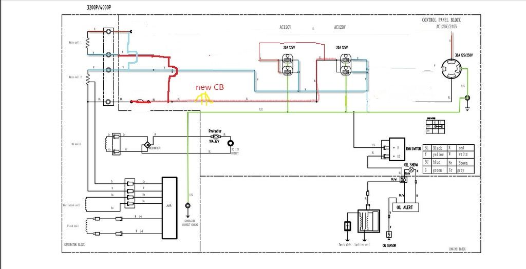
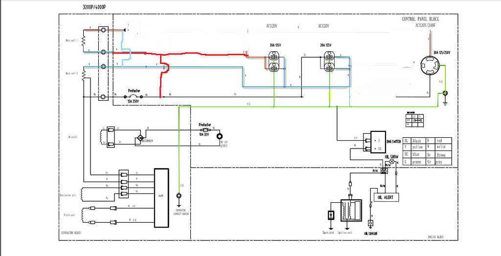
I'm trying to re-wire a HF generator to parallel. I have tried many things I found on this site as well as others and I just cant seem to get it to work. I have the wiring diagram but not sure how to get it on this forum. If anyone can help I can e-mail it to you.
What I have tried was to switch the wires as explained in the 3000W Chinese Gensets Info. topic on this site. I do that and I get 20 volts across the two outputs. I also read that if you get 0 to 50ish volts to switch a set of leads. I didn't try this and I'm not 100% clear on which two leads to switch??
To try and explain without the diagram, I have 4 wires coming out of gen head. Coil 1 has Red and White. Coil 2 has white and black. Red and black are power and whites are neutrals. Coil 2 is the only coil that the AVR monitors.
So at the terminal block, I take coil 1 red and coil 2 white and put them together, and coil 2 black and coil 1 white and put them together. When metering across the two I get 20 volts.
I have been testing at the terminal block figuring if I can get it to 120 volts there then I will worry about the rest of the plugs and things down stream.
Any help would be greatly appreciated.
Thanks all..
- Mark as New
- Bookmark
- Subscribe
- Mute
- Subscribe to RSS Feed
- Permalink
- Report Inappropriate Content
Nov-22-2015 09:09 AM
With standard synchronous generators,
You have to get both generator heads in phase
Think..turbines in a power plant
Dan near impossible with this type of generator
Takes specialized equipment
But I Can Not understand it for you !
....
Connected using T-Mobile Home internet and Visible Phone service
1997 F53 Bounder 36s
- Mark as New
- Bookmark
- Subscribe
- Mute
- Subscribe to RSS Feed
- Permalink
- Report Inappropriate Content
Nov-22-2015 05:21 AM
- Mark as New
- Bookmark
- Subscribe
- Mute
- Subscribe to RSS Feed
- Permalink
- Report Inappropriate Content
Nov-18-2015 09:12 AM
Disconnect the wires going to the old plugs
Connect the new external plug to the altered wiring on the terminal block
But I Can Not understand it for you !
....
Connected using T-Mobile Home internet and Visible Phone service
1997 F53 Bounder 36s
- Mark as New
- Bookmark
- Subscribe
- Mute
- Subscribe to RSS Feed
- Permalink
- Report Inappropriate Content
Nov-18-2015 08:54 AM
Thanks
- Mark as New
- Bookmark
- Subscribe
- Mute
- Subscribe to RSS Feed
- Permalink
- Report Inappropriate Content
Nov-17-2015 03:52 PM
- Mark as New
- Bookmark
- Subscribe
- Mute
- Subscribe to RSS Feed
- Permalink
- Report Inappropriate Content
Nov-16-2015 11:33 AM
But I Can Not understand it for you !
....
Connected using T-Mobile Home internet and Visible Phone service
1997 F53 Bounder 36s
- Mark as New
- Bookmark
- Subscribe
- Mute
- Subscribe to RSS Feed
- Permalink
- Report Inappropriate Content
Nov-16-2015 09:32 AM
I replaced the stock fuses with true 20 amp fuses and genny does what I need it too. Ran it several weekends now and have had no issues. Load still draws form one side of windings, but hasn't caused any problems yet.
I would still be interested in a conversion if anyone can come up with one..
hope that helps a bit..
- Mark as New
- Bookmark
- Subscribe
- Mute
- Subscribe to RSS Feed
- Permalink
- Report Inappropriate Content
Nov-11-2015 10:58 AM
road-runner wrote:Just buy this step down transformer/voltage regulatorThe specs are vague. This device kind of "quacks" like a 1,500 VA continuous, 3,000 peak VA device. I'm concluding this from its price, the fact that it weighs almost exactly half of a good quality 3,000 VA continuous transformer, and the following statements from the Amazon page:
-Maximum capacity is 3000-Watt including the power surge
-Remember to leave at least a 100-percent slack for the voltage converter transformer
-Televisions, heating appliances, laser printers and power tools spike when you turn them on. For these products you need to buy a voltage converter transformer that is at least 3-4 times the items capacity.
I'm curious what technology it uses for the voltage stabilization.
I believe these devices typically use a variac with the wiper controlled using a servomotor setup--basically a variac with a robot to adjust it to maintain an approximately steady output voltage. It's possible instead they use a multitap (auto)transformer and some sort of discrete switching circuit to switch in and out various taps, which is more or less equivalent but quicker acting and arguably more reliable.
- Mark as New
- Bookmark
- Subscribe
- Mute
- Subscribe to RSS Feed
- Permalink
- Report Inappropriate Content
Nov-11-2015 07:44 AM
Just buy this step down transformer/voltage regulatorThe specs are vague. This device kind of "quacks" like a 1,500 VA continuous, 3,000 peak VA device. I'm concluding this from its price, the fact that it weighs almost exactly half of a good quality 3,000 VA continuous transformer, and the following statements from the Amazon page:
-Maximum capacity is 3000-Watt including the power surge
-Remember to leave at least a 100-percent slack for the voltage converter transformer
-Televisions, heating appliances, laser printers and power tools spike when you turn them on. For these products you need to buy a voltage converter transformer that is at least 3-4 times the items capacity.
I'm curious what technology it uses for the voltage stabilization.
- Mark as New
- Bookmark
- Subscribe
- Mute
- Subscribe to RSS Feed
- Permalink
- Report Inappropriate Content
Nov-11-2015 07:37 AM
Reading the text I get the feelling you have a 120/240 volt generator you wish to re-wire for 120 volts and twice the amps (Both windings in parallel)
Need to be clear on this.
Sadly some of those overseas imports it's not going to work well cause they are not well designed.
2005 Damon Intruder 377 Alas declared a total loss
after a semi "nicked" it. Still have the radios
Kenwood TS-2000, ICOM ID-5100, ID-51A+2, ID-880 REF030C most times
- Mark as New
- Bookmark
- Subscribe
- Mute
- Subscribe to RSS Feed
- Permalink
- Report Inappropriate Content
Nov-11-2015 04:35 AM
3000 watts (though the reviews are sketchy).
- Mark as New
- Bookmark
- Subscribe
- Mute
- Subscribe to RSS Feed
- Permalink
- Report Inappropriate Content
Nov-11-2015 04:05 AM
Gdetrailer wrote:Dusty R wrote:
I have a Montgromey Ward 4000 watt belt generator that has a switch to change to 4000 watt 115v and no 230v, or 2-2000 watt 115v and 1 4000 watt 230v receptacle.
I'll see if I can find the manual tomorrow. It has the wiring diagram in it.
Dusty
Dusty,
I am 100% certain that your old school Monty Ward gen head will not be wired anywhere the same as these newer Chinese heads.. Most of the old gen heads often did not have AVR, kind of makes a difference..
I'm sure your right.
Dusty
I have a 10 yr old Chinese import which has AVR, it is 120V only.. I did look at rewiring with a switch to give me the option of 120/240 but the wires I need to get to are buried deep inside the gen head, they are not brought out as separate wires on mine.. Just too much work to tear it down that far.
- Mark as New
- Bookmark
- Subscribe
- Mute
- Subscribe to RSS Feed
- Permalink
- Report Inappropriate Content
Nov-10-2015 07:56 PM
clarify the wiring mods

But I Can Not understand it for you !
....
Connected using T-Mobile Home internet and Visible Phone service
1997 F53 Bounder 36s
- Mark as New
- Bookmark
- Subscribe
- Mute
- Subscribe to RSS Feed
- Permalink
- Report Inappropriate Content
Nov-10-2015 04:04 PM
Dusty R wrote:
I have a Montgromey Ward 4000 watt belt generator that has a switch to change to 4000 watt 115v and no 230v, or 2-2000 watt 115v and 1 4000 watt 230v receptacle.
I'll see if I can find the manual tomorrow. It has the wiring diagram in it.
Dusty
Dusty,
I am 100% certain that your old school Monty Ward gen head will not be wired anywhere the same as these newer Chinese heads.. Most of the old gen heads often did not have AVR, kind of makes a difference..
I have a 10 yr old Chinese import which has AVR, it is 120V only.. I did look at rewiring with a switch to give me the option of 120/240 but the wires I need to get to are buried deep inside the gen head, they are not brought out as separate wires on mine.. Just too much work to tear it down that far.
- Mark as New
- Bookmark
- Subscribe
- Mute
- Subscribe to RSS Feed
- Permalink
- Report Inappropriate Content
Nov-10-2015 03:58 PM
MrWizard wrote:
its two 120v windings
the voltage is the same in each winding
if it doesn't work,,and thats.. IF
then it is because the in the original configuration the avr was measuring between grd reference (center tap power windings neutral bonded to grd) and the tap point
the fix for that is to reverse the (as drawn) hot and neutral wires at the outlets
and bond that (new)neutral (the old hot) to the grd
creating a bonded neutral for reference point
just like the oem configuration except with parallel windings
i'll make a new drawing for this
use it only IF the the current drawing does not work
don't forget the double parallel circuit breakers in the hot side
must be both in the hot side, not hot and neutral, and not only one side, both hots must go thru a breaker before the receptacles
this drawing does not show the second breaker it must be in line of the first hot before they join
this drawing switches the phase of winding#1 instead of winding#2
this should work no matter what they are doing with the AVR
i don't like bonded neutrals on portable generators,
IMO ..its a safety hazard
Had a thought on the AVR..
Need to find out what the voltage sample is.. Then sub in a step down transformer with a secondary voltage that is close to what the AVR is needing.
Wire the primary of the step down to your 120V output, one would also need to make sure the transformer output has a ac waveform in phase with what the AVR is expecting..
I am pretty sure the reason the OP was not able to make it work is due to the way they tapped the winding for the AVR..
If the OP did not observe the correct phasing, the AVR may not be getting the correct sample in either voltage or phase.. Not sure how sensitive it may be to the phase..


