- Good Sam Community
- Everything RV
- Technical Issues
- Re: HF Predator mod to parallel
- Subscribe to RSS Feed
- Mark Topic as New
- Mark Topic as Read
- Float this Topic for Current User
- Bookmark
- Subscribe
- Mute
- Printer Friendly Page
HF Predator mod to parallel
- Mark as New
- Bookmark
- Subscribe
- Mute
- Subscribe to RSS Feed
- Permalink
- Report Inappropriate Content
Aug-04-2015 07:36 AM
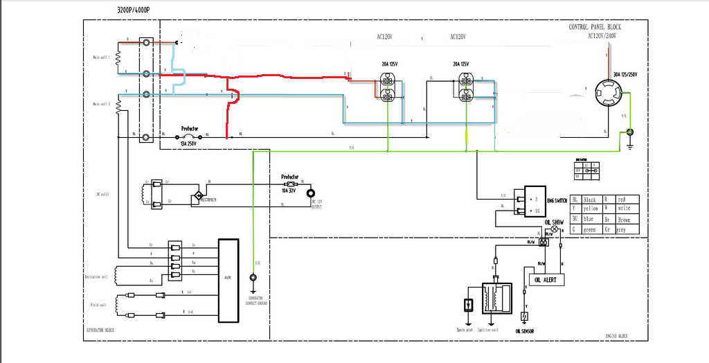
I'm trying to re-wire a HF generator to parallel. I have tried many things I found on this site as well as others and I just cant seem to get it to work. I have the wiring diagram but not sure how to get it on this forum. If anyone can help I can e-mail it to you.
What I have tried was to switch the wires as explained in the 3000W Chinese Gensets Info. topic on this site. I do that and I get 20 volts across the two outputs. I also read that if you get 0 to 50ish volts to switch a set of leads. I didn't try this and I'm not 100% clear on which two leads to switch??
To try and explain without the diagram, I have 4 wires coming out of gen head. Coil 1 has Red and White. Coil 2 has white and black. Red and black are power and whites are neutrals. Coil 2 is the only coil that the AVR monitors.
So at the terminal block, I take coil 1 red and coil 2 white and put them together, and coil 2 black and coil 1 white and put them together. When metering across the two I get 20 volts.
I have been testing at the terminal block figuring if I can get it to 120 volts there then I will worry about the rest of the plugs and things down stream.
Any help would be greatly appreciated.
Thanks all..
- Mark as New
- Bookmark
- Subscribe
- Mute
- Subscribe to RSS Feed
- Permalink
- Report Inappropriate Content
Nov-10-2015 03:01 PM
the voltage is the same in each winding
if it doesn't work,,and thats.. IF
then it is because the in the original configuration the avr was measuring between grd reference (center tap power windings neutral bonded to grd) and the tap point
the fix for that is to reverse the (as drawn) hot and neutral wires at the outlets
and bond that (new)neutral (the old hot) to the grd
creating a bonded neutral for reference point
just like the oem configuration except with parallel windings
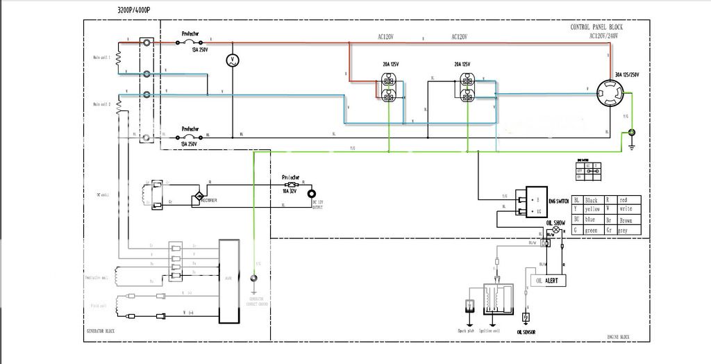
i'll make a new drawing for this
use it only IF the the current drawing does not work
don't forget the double parallel circuit breakers in the hot side
must be both in the hot side, not hot and neutral, and not only one side, both hots must go thru a breaker before the receptacles
this drawing does not show the second breaker it must be in line of the first hot before they join
this drawing switches the phase of winding#1 instead of winding#2
this should work no matter what they are doing with the AVR

i don't like bonded neutrals on portable generators,
IMO ..its a safety hazard
But I Can Not understand it for you !
....
Connected using T-Mobile Home internet and Visible Phone service
1997 F53 Bounder 36s
- Mark as New
- Bookmark
- Subscribe
- Mute
- Subscribe to RSS Feed
- Permalink
- Report Inappropriate Content
Nov-10-2015 02:35 PM
I'll see if I can find the manual tomorrow. It has the wiring diagram in it.
Dusty
- Mark as New
- Bookmark
- Subscribe
- Mute
- Subscribe to RSS Feed
- Permalink
- Report Inappropriate Content
Nov-10-2015 02:01 PM
MrWizard wrote:
your drawing was not to far off
here is the parallel changes
red is hot
black to blue is the neutral side
parallel means you parallel the windings, you have to break the center tap neutral and make new connections, the neutral & hot of the second lower pair switch places
i erased the lower / 2nd circuit breaker (it would now be in the neutral)
that needs to be rewired, both breakers go side by side together on the top red/hot
or replace the them with one 25amp breaker
remove the grd neutral bond inside the genset
i removed the twist lock completely
although that one or another one could be connected for 120v 25amp
twist lock
the avr measures both windings instead of just one {because the are wired in phase parallel}
OEM stock was series windings for 230v with center tap for neutral
this should work Unless there is some wire for the Avr deliberately missing from the circuit drawing
edit:
there is the possibilty that in the stock wiring the AVR is measuring the difference between the center tapped "bonded to ground", and its connection point in the winding,
switching that center tap neutral to a hot changes the reference voltage,
if the above drawing does not work, aka low voltage
contact me for a new drawing
reverseing the pahses and connectons
Most likely will not work.
The reason as to why it might not work is the AVR is sampling a SMALL voltage from a "tap" on the one winding.. It is not sampling the entire 120V output, just a small sample voltage.
Placing another parallel winding across will most likely result in the AVR getting an incorrect voltage sample.. due to slight variations in the winding resistance/reactance..
One would have to get a bit creative with how and what voltage the AVR is getting in order to make it work..
Could be as simple as two resistors in series across the 120V output to simulate a proper "tap" voltage..
- Mark as New
- Bookmark
- Subscribe
- Mute
- Subscribe to RSS Feed
- Permalink
- Report Inappropriate Content
Nov-10-2015 11:31 AM
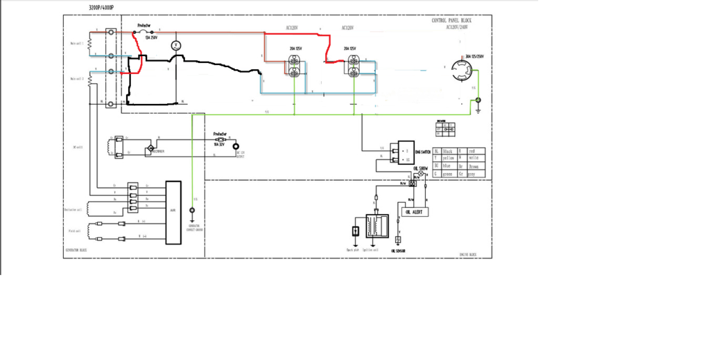
here is the parallel changes
red is hot
black to blue is the neutral side
parallel means you parallel the windings, you have to break the center tap neutral and make new connections, the neutral & hot of the second lower pair switch places
i erased the lower / 2nd circuit breaker (it would now be in the neutral)
that needs to be rewired, both breakers go side by side together on the top red/hot
or replace the them with one 25amp breaker
remove the grd neutral bond inside the genset
i removed the twist lock completely
although that one or another one could be connected for 120v 25amp
twist lock
the avr measures both windings instead of just one {because the are wired in phase parallel}
OEM stock was series windings for 230v with center tap for neutral
this should work Unless there is some wire for the Avr deliberately missing from the circuit drawing

edit:
there is the possibilty that in the stock wiring the AVR is measuring the difference between the center tapped "bonded to ground", and its connection point in the winding,
switching that center tap neutral to a hot changes the reference voltage,
if the above drawing does not work, aka low voltage
contact me for a new drawing
reverseing the pahses and connectons
But I Can Not understand it for you !
....
Connected using T-Mobile Home internet and Visible Phone service
1997 F53 Bounder 36s
- Mark as New
- Bookmark
- Subscribe
- Mute
- Subscribe to RSS Feed
- Permalink
- Report Inappropriate Content
Nov-10-2015 07:14 AM
Chuck
- Mark as New
- Bookmark
- Subscribe
- Mute
- Subscribe to RSS Feed
- Permalink
- Report Inappropriate Content
Aug-13-2015 11:10 AM
HF used to have a line of RED gensets like the Predators I'm seeing now, and a line of BLUE ones that seem to have been discontinued. I think I recall that some of the blue ones offered a 30-amp 120-vac outlet, but now I can't prove it.
It does seem that some of the Champion genny's offer 30-amp...
2003 Jayco Escapade 31A on 2002 Ford E450 V10 4R100 218" WB
- Mark as New
- Bookmark
- Subscribe
- Mute
- Subscribe to RSS Feed
- Permalink
- Report Inappropriate Content
Aug-13-2015 10:38 AM
I'm going to run as is. With the 20amp breakers it will run one of my RV air units with no problems. Got about 30 hrs on it and it's running well. Easily get 10 or 12 hrs on a tank of gas running one roof air. Enough power to run one air and second unit on fan as well as some lights.
I also have a 50amp RV so I can balance it a little buy running the air on one side and the other things on opposite side. Just takes some planning.
I would love to try the HF inverter generator they have out now. Looks like a good RV unit for the money. Only thing I don't like is the low run time due to small tank. Wonder if they have a fuel pump.. or maybe another project.. :@
So.. Although I think for an RV a 120 volt only unit or a switchable unit would work much better then the HF 3200/4000.. I must say so far I'm impressed with this HF generator. Well worth the money and with a 2 year warranty you really can't go wrong. If budget is a concern I would recommend taking a look at these generators. lots of folks complain about the HF generators and in their situation maybe rightfully so, but I can tell you I would consider the HF brand again.
on to the next project.. thanks all
- Mark as New
- Bookmark
- Subscribe
- Mute
- Subscribe to RSS Feed
- Permalink
- Report Inappropriate Content
Aug-10-2015 04:31 AM
MrWizard wrote:
Can you put up a picture of the OEM unaltered drawing
And yes the avr must be able to sense the voltage across the winding
That means neutral and hot
So im not sure I see the difference from the parallel wiring to the stock series wiring as far as the AVR goes. Unless it has to see a bounded neutral. With parallel you cannot have a bonded neutral correct??
- Mark as New
- Bookmark
- Subscribe
- Mute
- Subscribe to RSS Feed
- Permalink
- Report Inappropriate Content
Aug-06-2015 07:49 AM

- Mark as New
- Bookmark
- Subscribe
- Mute
- Subscribe to RSS Feed
- Permalink
- Report Inappropriate Content
Aug-06-2015 07:18 AM
And yes the avr must be able to sense the voltage across the winding
That means neutral and hot
But I Can Not understand it for you !
....
Connected using T-Mobile Home internet and Visible Phone service
1997 F53 Bounder 36s
- Mark as New
- Bookmark
- Subscribe
- Mute
- Subscribe to RSS Feed
- Permalink
- Report Inappropriate Content
Aug-06-2015 04:12 AM
Here is what I tested. I'm checking at the terminal block with everything else disconnected.

This is what I'm planning to test next. If I do this and don't see 120 volts or close to it.. then I believe I will call it quits and run generator how it is. I'm just not sure if this is any different then the first test above.
At this point it's one of those things I just can't let go..lol. It's been kind of a mission of mine.

- Mark as New
- Bookmark
- Subscribe
- Mute
- Subscribe to RSS Feed
- Permalink
- Report Inappropriate Content
Aug-06-2015 04:08 AM
The two whites are not connected when trying the parallel. The two whites are connected up towards the 240 plug and I have those wires disconnected from the terminal block when testing.
There are two sets of wires coming out of internal windings. They are separately sheathed. One set is red and white and they check out with continuity the other is black and white and they check out with continuity.
I think I am wiring it correctly for parallel. My thought is it might be the AVR keeping this from working. I don't know if the AVR needs to see the neutral. ???
other thought is maybe I cant stack the wires at the terminal. Maybe I have to use separate lugs and run a short wire and connect them together farther down the line. If that makes sense.
Not sure. I was hoping someone on here has had this issue before and could give some advice.
- Mark as New
- Bookmark
- Subscribe
- Mute
- Subscribe to RSS Feed
- Permalink
- Report Inappropriate Content
Aug-05-2015 02:04 PM
Are the measurements with the outlets etc. disconnected, or are they also connected to the wiring block?
Are the two whites connected together still after the attempted paralleling? That would be problematic (and possibly rather spectacularly so).
Also, are you sure you have the two whites associated with the coils correctly?
- Mark as New
- Bookmark
- Subscribe
- Mute
- Subscribe to RSS Feed
- Permalink
- Report Inappropriate Content
Aug-05-2015 11:28 AM
If I can get parallel at 70% I would be happy as the draw will be from both limiting the major unbalance I have know.
At least that was the plan.. lol
- Mark as New
- Bookmark
- Subscribe
- Mute
- Subscribe to RSS Feed
- Permalink
- Report Inappropriate Content
Aug-05-2015 11:17 AM


